
7 tips for Long Encoder Cable VFD applications
There are a number of issues that arise when a VFD and motor are mounted far apart. A previous post went over voltage spikes due to dV/dt of the drive’s PWM switching. The answer to that problem was a dV/dt choke or sinewave filter.
For closed-loop applications, another problem that can arise when a drive and motor are located far apart has to do with the encoder signals. Specifically, the voltage drop experienced on encoder signals.
This post will outline the problems of long feedback cable runs and how to address them.
Voltage Drop of Encoder Signals
The encoder cable is basically a transmission line carrying the encoder signal from the encoder device to the encoder card on the VFD. The encoder cable has some impedance which is a characteristic of the cable design.
The cable resistance should be listed on the manufacturer’s cable data sheet. The resistance is usually listed as some value per length – (e.g. Ohms/meter or Ohms/ft.). The longer the cable the more resistance it will have. And the more cable resistance, the more voltage drop the signal will have.
![]()
Standard KEB encoder cable resistance is called out in our manual
Let’s look at an example. Assume a worst-case scenario of a 200mA current draw. Using the data above for a 75-meter application, a TTL signal will lose 1.05V due to the voltage drop.
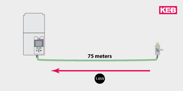
A long encoder cable run will cause the signal voltage level to drop
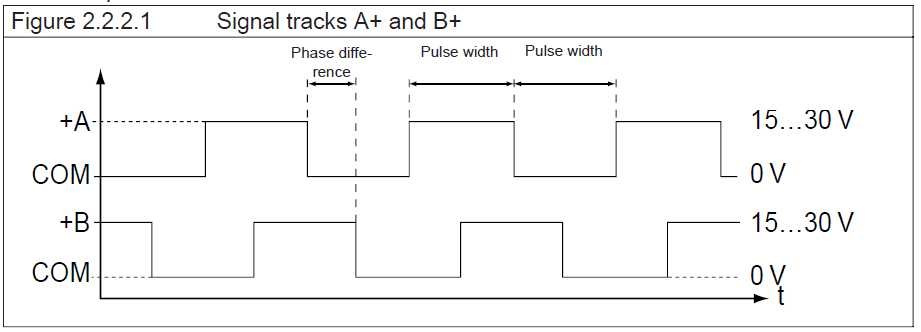
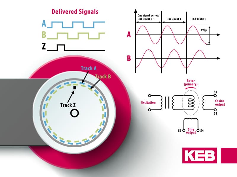
The most commonly used incremental encoders are the TTL type and have a target “on” voltage level of 5V. However, the drive’s encoder card will have an acceptable range on the voltage level that the drive or encoder input will accept. For example, KEB’s encoder cards recommend a minimum of 4.75V for the “High” TTL signal.
If there is too much voltage drop the TTL signals, you will get erratic operation and nuisance trips – the worst kind and a pain to troubleshoot. A common error is that the A or B channel compliment does not match the respective channel. With KEB F5 inverters, this will result in the E.EnC1 fault.
So if you are experiencing random encoder faults and suspect too much voltage drop, here are 7 things you can do to address the issue.
1. Use a Shorter cable
This one is simple but is worth mentioning because it might be the easiest to implement – if possible, use a shorter feedback cable. I’ve seen many applications where they use a “standard” cable or something they have on the shelf. The result is they use a much longer encoder cable than they really need.
An excessively long feedback cable can also couple unwanted noise and introduce other issues. So, use the shortest possible encoder cable that is practical for the application.
2. If Powered from the VFD – Increase the Supply Voltage
Some encoders receive power from the drives control/encoder card. The Push-Pull type TTL encoders will output a signal amplitude that is proportional to its supply voltage (i.e. there is no regulated supply onboard). With these types of encoders, there are effectively two conductor voltage drops – the supply, and the return.
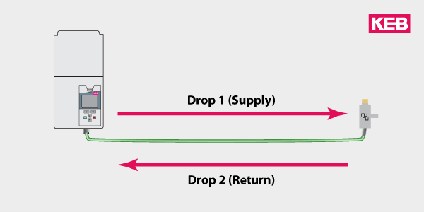
The voltage drop will be highest when the encoder is powered from the VFDs encoder card.
KEB’s F5 drive uses a fixed 5.2V supply to power the encoder. The idea is that the extra .2V compensates for some voltage drop. Some other encoder cards have means to increase the supply voltage.
If possible, you can adjust the encoder card supply voltage up. Just be sure to use a voltmeter to measure the supply voltage and check the encoder specs to make sure a higher voltage is permitted.
3. Apply power at the encoder
Another option (if supported by the encoder) is to apply the supply power directly to the encoder. Since the supply is directly applied to the encoder, this allows only one voltage drop on the feedback signals – effectively cutting the total voltage drop in half compared to the initial example.
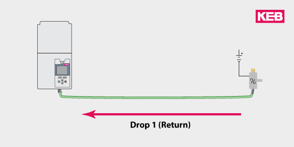
Applying power at the encoder can help reduce the voltage drop
Check your encoder datasheet to see how the encoder can be powered. Some encoders can only be powered from the drive’s encoder card. However, other encoders are designed to allow a direct power source. Some might even allow a higher input voltage like 24V but then regulate the output voltage accordingly (e.g. 5V).
So do check the encoder data sheet and see what the input power options are.
4. Consider using HTL logic
A “High” or “On” level for HTL logic is defined between 15V and 30V, with a target of 24V. KEB F5 HTL encoder cards will have a regulated 24V supply that can be used to power the encoder. Because the HTL signal is higher, it can support more of a voltage drop before hitting the lower “On” threshold.
HTL provides much more room for voltage drops – 9V from the regulated supply to the lower threshold (24V-15V = 9V). Compare that with TTL’s range of only 3V from supply to lower “High” threshold (5V-2V).
Just be sure that the drive’s encoder card supports an HTL input or the card could be damaged.
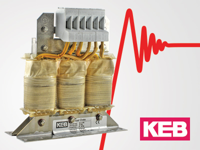
5. Use an Encoder cable with Lower Resistance
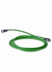
KEB offers special encoder cables for long distance runs. The cables use larger conductors so they have less resistance. Less Ohms/meter will result in less voltage drops on the feedback signal.
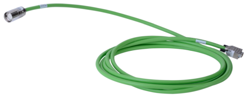
KEB offers feedback cables for long encoder runs
6. Use a signal repeater
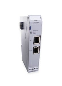
Another option is to use a signal repeater. Signal repeaters were commonly used before real-time fieldbuses like EtherCAT were available. They function by splitting, amplifying and conditioning the encoder signal.
KEB offers a signal repeater like this (00F4072-2008) that can be used for long run and multi-follower applications.
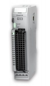
7. Use Fieldbus I/O – Like KEB’s Counter module
Another option is to use a fieldbus encoder module to transfer the data.
KEB’s EtherCAT encoder module allows the input of up to 2 TTL encoder signals. The encoder signal is wired to the module where it is converted and transferred via the EtherCAT bus.
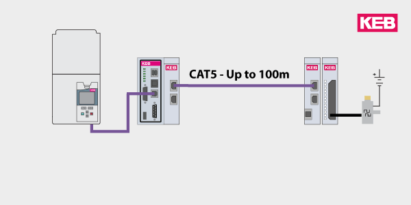
It’s possible to transfer the encoder feedback via the EtherCAT bus.
One big advantage with this solution is the low cost of a CAT5/6 cable. The cabling cost will be much less than a long encoder cable. The second advantage is that the position is now on the bus and available for use by the control without any other handling.
One consideration with this implementation is the input delay. The listed value for the input delay on the KEB module is 1ms. This will be suitable for most motion applications but you’ll want to verify it with your individual application.
KEB – A Solution Partner for Long Cable Installs
Contact a KEB America engineer today to discuss your application and our solutions.
Related Articles
Let's Work Together
Connect with us today to learn more about our industrial automation solutions—and how to commission them for your application.