

This is a continuation of our series on the special functions available with the KEB variable frequency drives (VFD). In this post we will look at the power off function.
Previous posts have included:
– UPS Function
– Brake Control
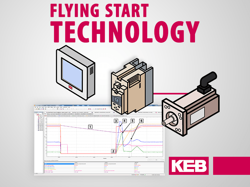
– Flying Start
– Quick Stop
– DC Injection Braking
– Flow Control
If the main power is lost to a VFD while the motor is under load, the DC bus of the VFD drops at an accelerated rate compared to no load conditions. When the DC bus reaches a low level, the VFD would shut down, disabling the output modulation and releasing the motor to coast to a stop. The motor coasting to a stop under the loss of main input power may not be of concern for many VFD applications.
However, consider an application utilizing electronic angular synchronization of mechanical axis or an application utilizing multiple VFD’s controlling a web of material. In these situations, a loss of input power resulting in motors coasting to a stop could result in mechanical binding or damage or potentially damage to the product.
Main power disruption to the VFD may be a minor occurrence, but the potential impact to the system may be substantial enough that it must be considered in the system design.
Power Off Function
The KEB Power Off function was developed as a solution to enhance the overall system design in applications that a loss of main power during normal operation could have a substantial negative impact.
The basic concept is that during a loss of main input power, the KEB VFD can utilize the rotational kinetic energy of the motor and connected load to power the VFD long enough to provide a controlled deceleration of the system. There may be some limitations to how much energy is available in the system, but utilizing the available energy to stop or slow the system could avoid a costly system issue.
In order to utilize this energy, the motor must act as a generator. In an induction motor, when the rotor speed exceeds the synchronous speed of the stator, the system acts as generator. In order to control the system in this situation, the rotor speed must be known. Thus the Power Off function is only available in systems running in closed loop control with a feedback device, or using a sensorless closed loop control without a feedback device like the KEB ASCL or SCL. By reducing the synchronous speed of the motor stator to a level below the rotor speed, the motor acts as a generator. The loss of energy back to the VFD results in the system decelerating to a stop.
Implementation
The KEB power off function, when initiated, replaces the speed control by a DC link control. The Power Off function reduces the stator synchronous speed below the rotor speed to maintain a programmed DC link voltage. A larger difference results in more regen energy. By adjusting the DC link control gain, response of the system can be modified to get the best use of the available regen energy.
Adjustable torque limits, during activation of the Power Off function, give additional function options to optimize the system. The KEB Combivis software also gives options as to how the system should respond if the main input power returns after the power off function has been initiated. The system can still be brought to a stop and an output fault initiated to indicate that the Power Off function was activated or, if operation constraints are met, the KEB VFD can bring the system back to normal operating conditions.
Example of the Power Off Function
An example of the Power Off function can be seen in figure 1. The KEB parameters shown in the example are (see programming manual for details on each parameter):
ru63 – DC voltage on power on
cu32.2 – DC voltage trigger level (in % of ru63)
cu32.3 – DC voltage reference level (in % of ru63)
cu32.5 – Stopping speed level
cu32.6 – Power off deactivation time
cu32.10 – Torque limit generating
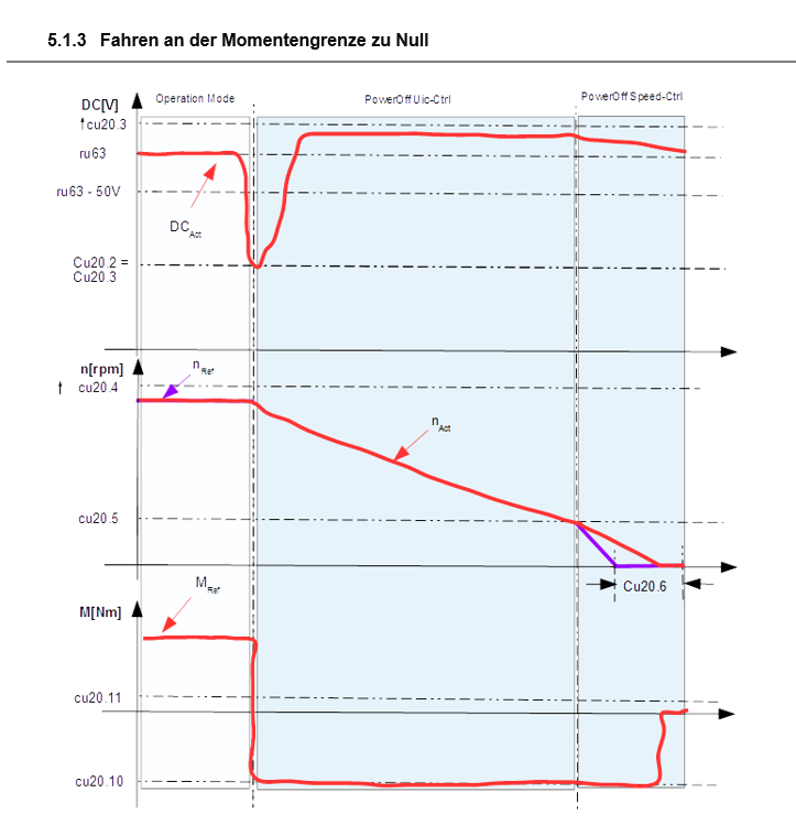 Figure 1 – Power Off function example[/caption]
During operation, the mains input power is lost. The DC bus immediately drops. When the DC bus level reaches the DC voltage trigger level, the Power Off function is activated in the drive. At this point, the DC link control replaces the speed control loop in the drive. The KEB VFD starts to decelerate the motor. Using the feedback information for the actual rotor speed, the VFD reduces the stator synchronous speed to a value below the rotor speed to move the motor into a generating state. By controlling the difference between the stator synchronous speed and the rotor speed, the KEB VFD can control the amount regen energy to keep the DC bus at the DC voltage reference level.
In figure 1, you can see the DC bus level rise as the motor speed starts to decelerate. In this example, a maximum generating torque is set in the KEB VFD. This maximum torque is reached and the KEB VFD does not increase the regen energy any further. In this case, the reference DC voltage is not reached but sufficient regen energy is available to bring the system to a controlled stop.
Once the actual speed reaches the stopping speed level, the DC link control is now replaced by the speed control loop with a set point of 0 rpm. The system is then brought to a stop. After the Power Off deactivation time is expired, a fault message can be initiated to the control system that a power off situation has occurred.
Conclusion
In VFD applications where a loss of main power during operation can have a substantial impact on the system components or performance, the KEB Power Off function may be the solution. Please contact a KEB engineer to discuss your application in further detail.
Related Articles


Let's Work Together
Connect with us today to learn more about our industrial automation solutions—and how to commission them for your application.