
Continuing our series on the special functions available with the KEB variable frequency drives (VFD), in this post we will look at the brake control.
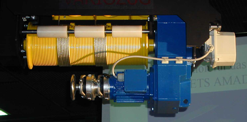
The KEB Combistop brake is the industry leader in electro-magnetic holding brakes for applications utilizing industrial electric motors. The KEB Combistop electromagnet brake is part of a complete line of industrial power transmission products available from KEB. The comprehensive product offering from KEB provides a single source for complete solutions to industrial power transmission applications. KEB had developed this product offering for ease of integration and superior performance.
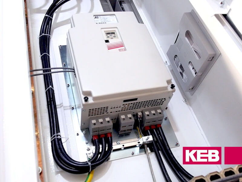
An example of how KEB integrates components across the product line into a complete solution is the brake control function available in KEB variable frequency drives.
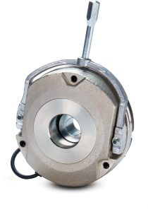
For applications that require lifting or lowering or any application that may require the use of a brake, the KEB VFD can be programmed to handle the brake control. The KEB Combistop brake uses mechanical spring force in combination with a friction disk to provide the holding torque for the application. An electromagnet is used to overcome the spring force to allow the friction disk, which is connected to the motor shaft, to spin freely. When the power is removed from the electromagnet, the spring force is again applied to the friction disk, producing the braking torque. For more information on the KEB Combistop, you can watch this video from our YouTube channel.
While the Combistop brake does have dynamic braking capabilities, it is typically used in static braking applications that require a holding torque at zero speed. In these applications, the brake is engaged/disengaged at zero speed. Because the brake utilizes friction to provide the braking torque, engaging the brake at a non-zero speed (dynamic braking) does result in some incremental wear to the friction surface. This incremental wear will add up over time resulting in reduced braking capabilities. The KEB Combistop brake can be adjusted to bring the braking torque back to nominal values, but at some point, the wear parts (friction disk, friction surfaces) must be replaced.
Because the Combistop utilizes mechanical means (springs) to provide the force for the braking and an electromagnet to overcome the spring force to release the brake, there is a short time before full torque is available during engagement and also before the brake is fully released during disengagement. This engagement and disengagement time is due in part to the time it takes for the electromagnetic field to be developed or dissipate respectively.
If an application utilizes a VFD and a brake on the motor, if there is no integration of the operation of these components, it is possible for the VFD to start the motor while the brake is still engaged. Even if there is still braking torque only for the short disengagement time, this can still result in incremental wear to the friction surface, which, over time, can cause the degradation of the available braking torque. In addition, during the time that the VFD stops the load and the brake is to engage, if the VFD releases the load before the braking torque has fully developed, the load may move, which can cause issues in the operation of the system.
In order to solve these issues and provide the maximum lifetime of the brake wear surfaces, KEB has developed a programmable brake control system available on the KEB VFD products. In order to provide the highest level of flexibility to optimize the brake control function, the function is separated into five main programmable components:
- Brake premagnetizing time
- Brake release time
- Brake engage delay time
- Brake engage closing time
- Brake engage fadeout time
Component 1 and 2 are used during the brake open or release time (brake torque disengaged). Component 3, 4, and 5 are used during the brake closing, or engagement time (brake torque engaged).
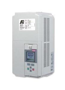
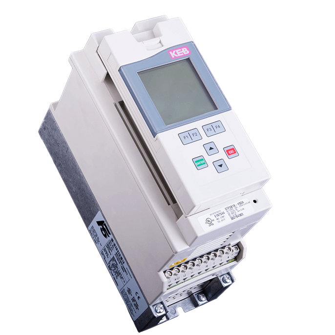
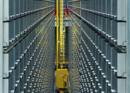
The KEB VFD can control the motor using either open-loop or closed-loop control. Depending on the control mode used, the above components are set up differently. As an example, we will look at a system consisting of a KEB F5 VFD, KEB induction motor with rear mounted KEB Combistop brake. The application will be a hoist system in which a load is moved vertically in the upward and downward direction using volts/Hz control of the motor (open loop). In this case, the KEB VFD brake control incorporates two additional components to the brake control:
- Brake release start frequency
- Brake engage start frequency
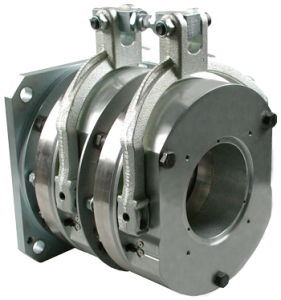
The KEB Combistop brake product line ranges from 5Nm up to 1500Nm torque. To accommodate the various voltage options for the KEB Combistop brakes, the KEB brake control system utilizes an external relay (solid-state or mechanical contact) which switches the required brake voltage. The external relay then utilizes a 24vdc control voltage which is controlled by the VFD brake control function utilizing a control relay on the KEB VFD control terminal strip. The external relay is not included with the KEB VFD.
With the brake control activated in the KEB VFD, the control of the brake starts when the KEB VFD is enabled and the command to run the motor is given. Let’s look at each of the components of the KEB brake control:
- Premagnetizing time. The premagnetizing time allows time is used to allow time for the flux to build up in the air gap of the induction motor.
- Brake release time. The brake release time defines the time from connecting the voltage across the brake coil to the time the brake torque starts to decrease. The drop-off time from this point is very steep as this is the point the armature has moved across the brake airgap allowing the friction disk to rotate freely. This value is available in the KEB documentation for the specific brake model.
- Brake engage delay time. The brake engage delay time allows for the system to handle any dynamic effects during stopping or if the motor does not follow the deceleration ramp from the VFD exactly.
- Brake engage closing time. The brake engage closing time is the time from when the voltage across the brake coil is removed to the time the brake reaches full torque. This value is available in the KEB documentation for the specific brake model.
- Brake engage fadeout time. After the brake engage closing time has expired the fadeout time starts. During the brake engage fadeout time, the motor current is brought to 0 (see brake engage start frequency below). After the fadeout time reaches zero, the modulation remains on for another 100msec. This allows any noise that may occur during the motor stopping to decrease.
When using the brake control in volts/Hz operation of an induction motor, in order to hold the load a low output frequency must be sent to the motor to build up the required motor torque. The frequency level to reach the required holding torque is dependent on the motor characteristics. See the KEB application manual on how to determine the required value.
- Brake release starts frequency. The brake release start frequency defines the required frequency level that the VFD will output to the motor to provide sufficient torque to hold the load without movement. This value is defined by slip speed and the required holding torque. Once this value is optimized, the output frequency from the VFD will be sufficient to maintain a holding torque equal to the static torque of the load.
- Brake engage start frequency. The brake engage start frequency defines the required frequency level that the VFD will output to the motor to provide sufficient torque to hold the load without movement. This value is defined by slip speed and the required holding torque. Once this value is optimized, the output frequency from the VFD will be sufficient to maintain a holding torque equal to the static torque of the load.
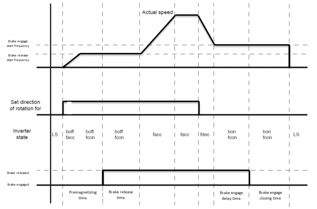
Below is a graphical example of the brake control function in use. When the KEB VFD is given the signal to start the motor, in this case, a forward input, the premagnetizing timer begins. During this time the drive ramps the output to the motor to the brake release start frequency. Once the premagnetizing time has expired, the control relay of the F5 energizes the external relay controlling the brake voltage. The brake is then released.
After the brake release time has expired, the VFD then runs the motor up to the programmed set speed. When the VFD is commanded to decelerate the motor to a stop, in this case by removing the forward input, the VFD starts to decelerate the motor. The VFD decelerates the motor to the brake engage start frequency. Once the brake engage start frequency is reached, the VFD holds this output frequency and the brake engage delay timer starts. This allows the load to reach a steady state.
After the brake engage delay time has expired, the control relay switches to remove the voltage from the brake coil and the brake engage closing time starts. During the brake engage closing time, the output frequency to the motor remains at the brake engage start frequency. Once the brake engage closing time has expired, the brake engage fadeout time starts and the current to the motor is reduced to zero and the modulation to the motor is removed.
Conclusion
Without the KEB brake control function included in the KEB VFD F5 drive, implementing this procedure would require some additional logic control external to the VFD. Incorporating this function into the KEB VFD programming reduces the machine logic control requirements, possibly eliminating additional PLC control. The KEB brake function also maximizes the life of the brake reducing downtime and increasing system efficiency.
Please contact a KEB Application Engineer to discuss your application today.
Previously in this series
Application notes: Speed search
Also known as “flying start,” the speed search function of KEB VFDs helps to mitigate issues that arise from a motor coasting when output modulation is removed.
Related Articles
Let's Work Together
Connect with us today to learn more about our industrial automation solutions—and how to commission them for your application.