
Controlling a Yaskawa Sigma 5 Servo Motor – with KEB F6-K Drive
KEB has a reputation for being able to run many different motor types from many different motor manufacturers. This includes induction motors, salient pole servo motors, interior pole servo motors, linear motors, and synchronous reluctance motors.
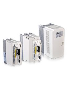
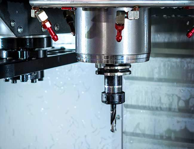
We were able to prove that again recently by helping with a retrofit opportunity that involved running a Yaskawa Sigma 5 servo motor on a Grinding machine.
This blog post will describe the steps taken to solve the application and how those could apply to other retrofit solutions.
Application Description
For this retrofit application, KEB was contacted to replace a Yaskawa Sigma-5 servo amplifier. The amplifier was being used to run a Yaskawa brushless servomotor in closed loop speed control using incremental encoder feedback. The stated reason for the retrofit was because the machine tool OEM was unhappy with the lifecycle of the original VFD.
Drive Selection
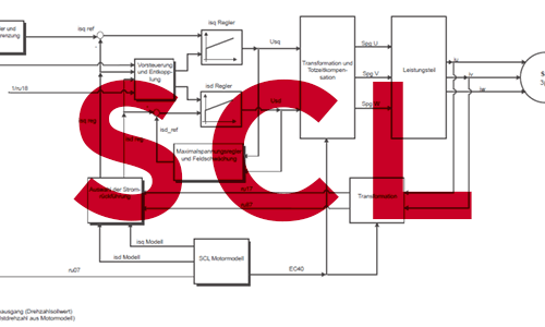
The first issue with replacing the drive was that the existing encoder was proprietary and the servomotor couldn’t be run in open loop. However, this made the application an ideal fit for KEB’s Sensorless Closed Loop (SCL) control.
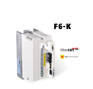
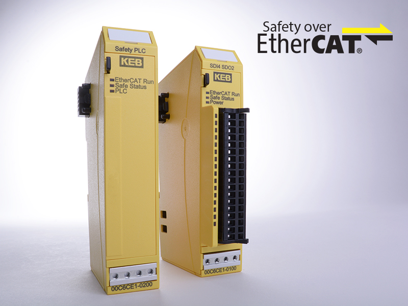
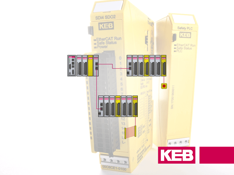
SCL provides closed loop speed control, without requiring encoder feedback. The application also required EtherCAT communications, so KEB’s F6K was the perfect solution. The F6K comes standard with EtherCAT onboard, an all-in-one control firmware that includes SCL, and additional benefits such as SIL3 Safe-Torque-Off.
F6K Programming
Motor Identification
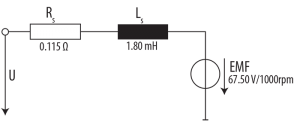
Once the drive was selected and received by the customer, the programming could begin. In order to start the SCL control, a motor identification by the drive is typically required. This allows the VFD to make an equivalent circuit diagram so the motor model, and thus the motor control, is more accurate.
 The motor identification requires the input of basic nameplate data, which in the case of a PM motor is: rated current, rated speed, max current, rated voltage, rated torque, rated frequency, and max torque. Unfortunately for this case, not all of the required values were published, so a workaround was required. After learning the number of pole pairs in the motor, the rated frequency could be calculated, and the motor identification could be tested until successful.
Rotor Detection
Once the motor identification was complete, it was possible to begin running the motor. The next hurdle was the rotor detection. Upon each startup of a synchronous motor, the drive must determine the system offset. When there is feedback, the offset is the mechanical difference between the rotor position and the position of the installed encoder. This offset doesn’t change between runs and is stored in a drive parameter.
For SCL operation, the rotor aligns to a defined starting position before ramping up to the command speed. There are three ways to do this in KEB’s generation 6 drives: constant voltage vector (cvv-default for SCL), five-step, and high-frequency injection.
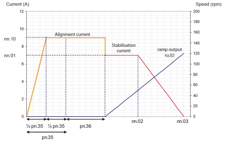
When using the default cvv, every 5-10 startups there would be a growling noise from the motor and the rotor detection would fail. During cvv, a voltage vector with constant electrical position is output to the motor. To troubleshoot the detection failures, adjustments were made to the amount of current used during alignment and the amount of time the current was built up and held. Minimal differences were noticed while changing these values, so the rotor detection was switched to five step.
The five step method uses the saturation of the motor for detection of the rotor position by applying five different voltage vectors within a few milliseconds. In this method, the possible adjustments are the current and error threshold. The current is desired to be as high as possible without causing too many overload or overcurrent errors, since a higher current causes higher saturation and thus more precise identification. The error threshold should be as low as possible, without being too low where it causes an identification failure too often.
After switching to the five step method and finding a good balance between these two values, the rotor detection errors were almost completely eliminated.
Application Specific Adjustments
After troubleshooting the rotor detection, it was possible to move onto the more standard adjustments for the application. The most important change was increasing the proportional and integral gains so the drive responded quickly to load changes. Other changes included application specific data such as torque limits and acceleration rates. Once the adjustments were complete, the customer was satisfied with the performance and the retrofit was deemed a success.
While these specific adjustments may not be necessary on every retrofit, they show how the drives from KEB America can be successfully used in all applications with the help of an Application Engineer.
KEB Drives for Retrofits
If you have questions about a new or existing project that could use KEB’s expertise, contact us today.
Related Articles
Let's Work Together
Connect with us today to learn more about our industrial automation solutions—and how to commission them for your application.