
Many people take ride quality for granted when they ride in an elevator. A smooth and responsive ride requires precise adjustment from all system components such as the controller, variable frequency drive, and brakes.
The variable frequency drive or VFD, can be a powerful adjustment tool for mechanics when properly applied. This article will specifically focus on software functions available in an elevator VFD for two main elevator adjustments; rollback and increased speed control response.
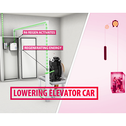
Watch the video below to understand how synthetic pre-torque can be used to eliminate rollback.
Elevator Car Rollback
Rollback can occur for a brief moment at the beginning of the ride when the brake lifts, a speed command has not yet been initiated, and the VFD has not built up enough holding torque to prevent the car from moving in the direction of weighting. This may be felt as a bump by passengers in the car during takeoff. Rollback is more noticeable on permanent magnet gearless motors than induction geared motors due to the lower starting friction of gearless machines. Rollback can be diagnosed visually if the elevator controller is located in the machine room along with the motor. However, in machine room-less (MRL) applications, diagnosing rollback may be more difficult since the motor is out of sight. Inverter scoping software can aid in identifying and adjusting for rollback. Figure 1 below provides a visual representation of rollback using a four channel scope trace showing command speed (red), actual motor speed (blue), motor torque (green), and motor position (yellow).
The motor position (yellow) starts to deviate from zero before the speed command is given, indicating the brake has lifted and not enough holding torque (green) is present to hold the car at zero speed. There are several torque bumps present in response to motor movement when the brake was lifted, which can cause a bump to be felt by passengers on takeoff.
Adjusting for Rollback
There are several ways to adjust for rollback. For example, brake and speed command timing may be adjusted such that as the brake is lifting, the car begins to move. While this may reduce the effects of rollback, it doesn’t address the root cause and still doesn’t provide a smooth takeoff for passengers. Luckily, depending on VFD manufacture, the software can be used to eliminate rollback.
Most elevator drive manufacturers have some method of providing a torque command, while under the brake or immediately after the brake picks to eliminate rollback. The following paragraphs describe different methods of providing holding torque to prevent rollback.
Feedback Control Loop to Reduce Rollback
One method involves using a feedback control loop. A feedback control loop consisting of both a proportional and integral coefficient can be used to provide the motor with adequate holding torque, thus preventing rollback. When this method is used, movement of the car is necessary to make the function work properly. This may seem counterintuitive at first, but the movement is very small. This movement cannot be seen to the naked eye (as the sheave rotating) or felt by passengers riding in the car. Figure 2 below shows a scope trace of torque buildup in response to movement.
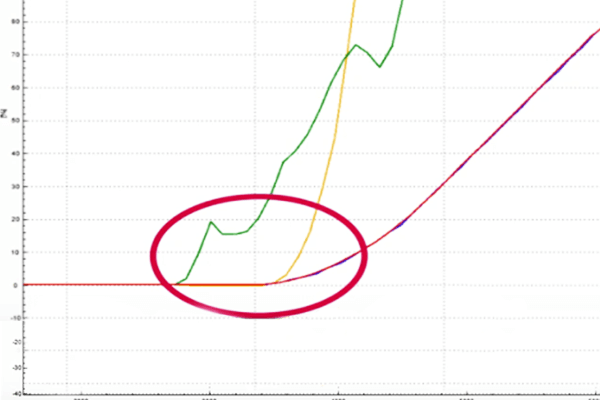
Figure 2: Properly adjusted pre-torque settings, without any rollback on scope trace. Command speed (red), motor speed (blue), motor torque (green), motor position (yellow).
Based on the amount of movement detected from the motor encoder, the drive will quickly ramp torque (green) to hold the motor at zero speed. This is done by adjusting the integral coefficient of the feedback control loop or ‘gain’. The integral response accumulates error, in this case, non-zero speed, over time. Higher integral gain values will ramp the torque faster to accommodate for the non-zero speed error until a steady-state situation is reached (zero speed). All of this happens very quickly, within 0.3 – 0.5sec, meaning passengers do not feel anything. This method of providing torque when the brake lifts works very well for most elevator applications. However, its basic functionality, a PI feedback control loop, relies on error (motor movement) to function.
Using a Load Weigher to Reduce Rollback
Another method of providing torque involves using a load weigher. A load weighing device uses sensors to detect the amount of load in the car, and can provide a precise holding torque response based on different loading conditions. Depending on the type of load weigher used, it can connect directly to the VFD and transmit a torque command via an analog signal or it can be connected to the controller where further filtering can be applied, and then a resulting torque command can be sent to the drive via serial communication.
Increased Speed Control Response
For most elevator applications, the standard proportional, integral, and derivative (PID) gains in the feedback control loop in a VFD provide adequate speed control response. However, for some high-profile elevator applications (high-end office buildings, apartment complexes, etc.), additional elevator ride quality adjustment tuning may be necessary to achieve the desired result, such as aggressive floor to floor times.
A traditional PID feedback control loop relies on feedback from the motor encoder to make speed control adjustments based on the difference between command speed and actual motor speed from the encoder. This difference is called error. The VFD’s response to this error is adjusted via proportional and integral speed control gains. While this method of speed control works well, it relies on the feedback from the motor encoder for speed control. For some high-performance applications, traditional PI control may not provide the desired speed control response. For these types of applications, a more sophisticated speed control method can be used.
Learn more about KEB feed-forward torque control by watching the video below:
Feed Forward Torque Control (FFTC) can be used to provide added speed control response. FFTC reduces the dependence on speed feedback from the motor encoder by predicting what the system will do, based on the system inertia, and providing the required torque command based on that prediction. Figure 3 below provides a block diagram of how FFTC works.
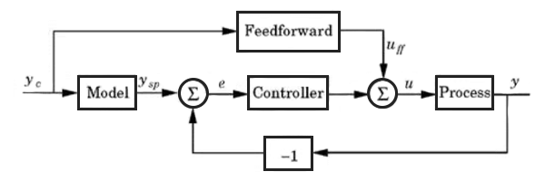
After the system inertia has been learned by the VFD, FFTC can be activated. By modeling the motor data, ysp, the system response, uff, with the system inertia, a prediction of the response can be made. A pre-correction is made before the motor encoder feedback is received, reducing the amount of error. This method of speed control provides a more accurate response with less reliance on the proportional and integral gains.
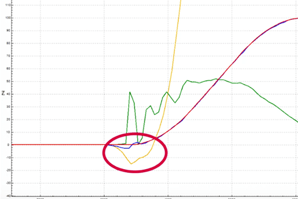
To show how effective FFTC can be, a detuned motor was set up in a controlled R&D lab setting, with low-speed control gains and FFTC turned off. No additional adjustments were made to the motor. Figure 4 below shows a scope trace of the command speed (red), actual motor speed (blue), motor current (yellow), and motor torque (green) of a simulated elevator run.
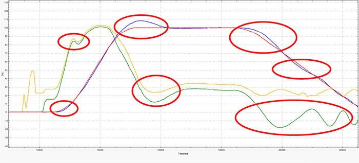
Significant amounts of undershoot and overshoot are present on both the acceleration and deceleration portions of the profile (circled). Additionally, these areas of undershoot and overshoot correspond to large torque bumps that can negatively impact ride quality.
Next, to show the impact of using FFTC, the system inertia was learned and FFTC was activated. The same run was performed and scoped below in Figure 5.
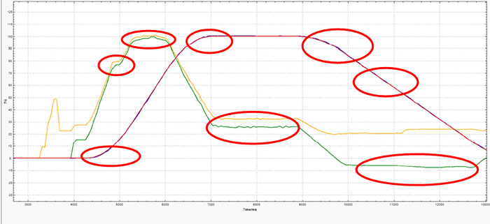
Activating FFTC drastically reduces undershoot and overshoot that were present in the acceleration and deceleration portions of the profile. Also, the magnitude of the torque bumps are much smaller, with smoother torque transitions providing a much more comfortable ride for passengers. While this is an exaggerated case and done under lab conditions, it shows the basic principle and impact FFTC can have on elevator speed control.
Adjustments such as a low pass filter can be set to further improve ride quality. When the speed profile is generated externally by the controller, increasing the sample time of the low pass filter can help reduce any unwanted effects from discontinuous inflection points on the speed profile generated by the controller. Additionally, FFTC also features a gain value that can be used to strengthen or weaken the response of the feed-forward torque command.
In general, activating FFTC makes the elevator system more responsive. The speed gains will have less effect and adequate speed control can be maintained over a wider range of gains. FFTC works well in applications featuring aggressive speed control profiles and applications exhibiting high starting friction, such as induction geared machines.
Conclusion
The VFD is a powerful elevator ride quality adjustment tool that can provide solutions to two common elevator ride quality problems. Rollback can be eliminated using a PI control loop in the VFD. Additional tools such as load weighers can also be used to eliminate rollback. For highly dynamic elevator applications, FFTC can provide added responses to achieve desired ride quality. Additional adjustments such as low pass filters and gains can fine-tune the ride for the best possible passenger experience.
Related Articles
Let's Work Together
Connect with us today to learn more about our industrial automation solutions—and how to commission them for your application.