EMC Considerations for Auxiliary Inverters in Electric Vehicles Applications
Once upon a time, just about everything in a vehicle was mechanical, most notably the combustion engine which provided power to other subsystems such as pumps for power steering and compressors for air conditioning. But as technology progressed and fuel consumption and emission standards became more stringent, electric components started to take over. A prime example of this has been the use of computer-controlled fuel injection systems replacing carburetors.
The Future is Electric
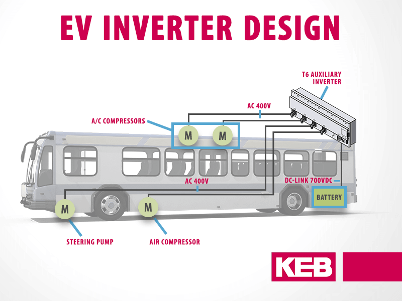
Fast forward to the present where all-electric vehicles are rapidly on the rise with batteries replacing fuel systems, inverter-driven electric motors replacing the engine and auxiliaries such as pumps and compressors, and an ever-important vehicle control unit controlling it all. But, to make this new electrically-dense environment work properly, it is increasingly important to consider EMI and EMC in the design and layout of these systems.
What is EMI and what are its effects?
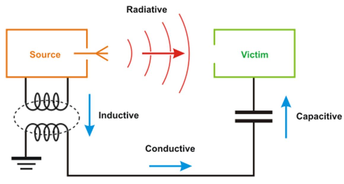
EMI is electromagnetic interference. There are two primary types of EMI, radiated and conducted.
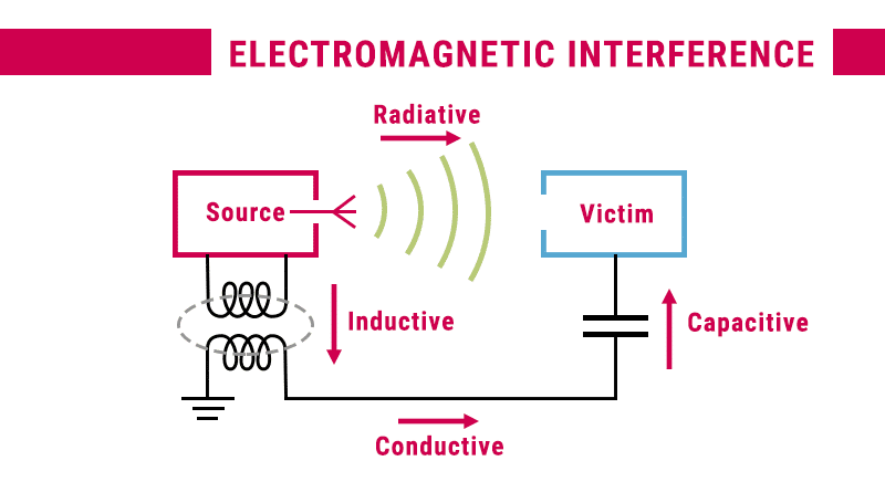
Radiated emissions (also known RFI, radio frequency interference) are associated with the magnetic field generated by current flowing through a wire. Like radio waves, radiated emissions can transcend space and be picked up by other devices in proximity. The effect is that radiated emissions can induce fields which can disrupt communication signals and/or negatively affect the operation of the receiving devices themselves. Of particular concern would be the critical vehicle control unit and CAN bus communication. Additionally, this can also limit options to the spatial outlay of components.
Conducted Emissions
Conducted emissions, on the other hand, travel along a path such as a wire or plane connecting devices. These emissions include transient current and voltage from high frequency switching devices, such as the pulse-width modulation of inverters, coupled through parasitic impedances. The effect is that with a path to travel back to the DC grid, these conducted emissions can excite system resonance points. This can lead to voltage or power peaks which may cause damage or lead to reduced lifetime of other DC-connected devices. Conducted emissions are of particular concern since the primary electric vehicle components including the inverters, electric motors and power supply are all interconnected as a path for conducted emissions.
What is EMC and why is it important?
EMC is electromagnetic compatibility. That is, all devices in an electrical environment should not adversely affect the operation of others. It is the golden rule of electronics playing nice in the sandbox. This applies to all electronic devices and is important because the ultimate goal is the reliable operation of the system as a whole. To ensure this, there are international standards and type approvals for components to ensure EMC homologation requirements are met. Therefore, it is important to select components meeting EMC type standards such as ECE-R10 and CISPR 25.
…all devices in an electrical environment should not adversely affect the operation of others. It is the golden rule of electronics playing nice in the sandbox…Therefore, it is important to select components meeting EMC type standards such as ECE-R10 and CISPR 25.
How can EMI be mitigated?
Although EMC applies to all devices in a system, power electronics with high frequency transistor switching such as inverters for the propulsion traction motor and auxiliaries are the primary producers of EMI in electric vehicle applications.
A good EMI mitigation solution goes both ways though…keeping internally generated noise in and keeping externally generated noise out…and techniques may depend on the source and type of emission.
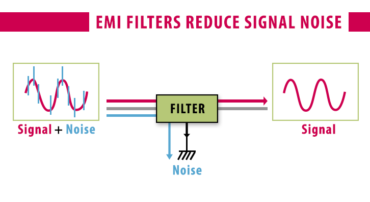
DC Filtering
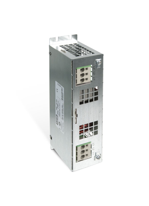
A DC choke is a good option for mitigating conducted emissions generated from inverters. A DC choke allows low frequency DC voltages and currents to pass through. This keeps in noise generated by the device from going out to the DC grid. Blocking the harmful high frequency and leakage currents prevents harmful or disruptive effects to other devices connected on the grid. Additionally, the choke blocks noise from coming into the device from other external noise sources.
Shielded Motor Cables
The motor cables carrying high-frequency switching power from an inverter to a motor present a ripe source for transmitting radiated emissions. This noise can possibly affect any device in the vicinity of the cable run, particularly other power cables or low voltage communication signal cables running closely in parallel. Braided shielding around the power conductors acts as a net to capture and provide a low-resistance path to ground for the radiated electromagnetic emissions generated by the current in the conductor. Likewise, it also acts as a barrier to reflect any external emissions from being received. There are many other considerations in selecting motor cables, but shielding is only effective as its weakest link so shielded connectors and cable clamping also need consideration.
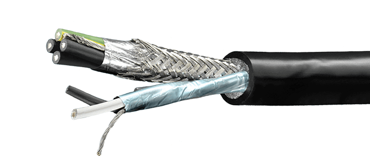
Shielded VFD cables like this example from Belden
Unshielded motor cables, on the other hand, can wreak havoc on low signal vehicle communication signals and networks such as the CAN bus. Additionally, unshielded motor cables can limit the distance between inverter and motor putting. This puts additionally constraints on device layout such as needed to distributing auxiliary inverters, which adds additional cabling costs and design complexity.
What to look for in auxiliary inverter design?
EMC design should be a priority and not an afterthought. Without proper electromagnetic compatibility in-vehicle electric systems, it is not a matter of “if” EMI issues will arise but “when”… and can result troubleshooting headaches to resolve and costly redesigns to root out. Therefore, it is important to consider EMC at the design stage and likewise select system components which share this philosophy.
EMC Testing
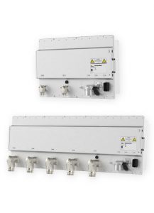
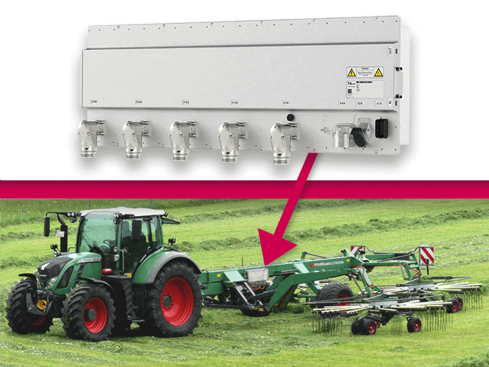
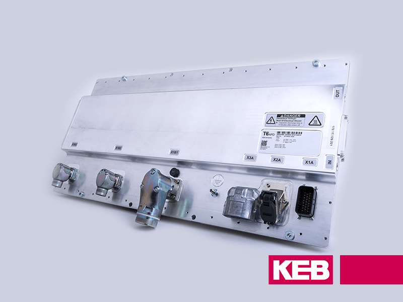
KEB is a company experienced in the design of inverters and filter solutions for a variety of specialized and high-tech applications across several industries. With this experience in mind, the T6 inverter was specifically designed for controlling the auxiliary motors (pumps, compressors, e-PTO, etc.) in commercial electric and hybrid vehicles and providing EMC solutions has been part of the design process from the start.
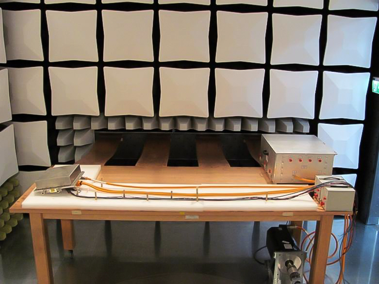
KEB’s testing chamber for EMC considerations for Electric Vehicle applications
Conclusion
Each T6 auxiliary inverter has an internally integrated DC common-mode EMC filter as standard design and the T6 meets CE, ECE R10 (E1) and CISPR 25 type standards for EMC and emissions as well as meeting even more stringent OEM standards which can be tested in-house. KEB also sources high-quality DC and motor cables and connectors, providing customers with a ready-made solution.
In addition, the motor cables are tested and approved with the T6 for lengths up to 30 meters. This allows users to leverage the benefits of a central, multi-axis auxiliary inverter with a single DC input, coolant connection, and CAN ID as opposed to individually distributed auxiliary inverters with parallel connections which add to system cost, design complexity, and makes electromagnetic compatibility of multiple devices more difficult to integrate into the system. The KEB T6 auxiliary inverter provides an integrated system solution that is scalable from 1 – 6 inverter outputs in a single housing with three modular power stage options (7.5 kW, 15 kW, 30 kW) for each output. With this flexibility and EMC design, the T6 provides a reliable solution for a variety of EMC considerations in Electric Vehicle applications. Commercial electric vehicles such as transit buses, heavy-duty trucks, and refuse collection vehicles.
Let's Work Together
Connect with us today to learn more about our industrial automation solutions—and how to commission them for your application.
