
Encoder Position for Permanent Magnet Motors in Elevator Applications
Permanent magnet (PM) motors have become popular options in elevator applications over the years due to their increased efficiency and performance characteristics. Since a PM motor’s rotor is magnetized by permanent magnets, rather than induced, the variable frequency drive (VFD) must know the rotor position in relation to a stator pole pair to modulate at the correct commutation angle to produce maximum torque output. The rotor position can be determined by an absolute position encoder mounted on the motor shaft.
This article explains how the PM motor rotor position is measured with the VFD and identifies common problems associated with incorrect encoder position.
Why does the VFD need to know rotor position?
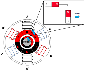
PM motors consist of a rotor with permanent magnets mounted on the surface (or internal to the rotor, IPM machines) and stator coils which are magnetized by current output by the VFD. The interaction between rotor permanent magnets and stator electromagnet fields follow the general laws of magnetism where opposites attract and like forces repel. Then, as the drive modulates the output voltage frequency, a rotating magnetic stator field is created to produce torque. But, the proper stator magnetic field commutation angle is necessary for maximum torque output. Maximum torque output occurs when the stator and rotor magnetic fields are 90° from each other, as seen in Figure 1. Otherwise, if the angle between the stator and magnetic fields is greater or less than 90°, more current must be applied to the stator to create a stronger magnetic field to produce the same amount of torque.
Therefore, the rotation of the three-phase AC voltage applied to the stator winding must be exactly synchronized (e.g. electrically commutated) to the rotation of the PM field on the rotor. This can be accomplished by using an absolute position encoder mounted directly to the motor shaft. Absolute position encoders have a channel pair in addition to the typical speed channels for single-turn rotor position and a reference procedure must be performed during startup so that the drive has a position value corresponding to a known position, such as a motor pole, which is then used as an offset reference. The physical relationship between the motor shaft and encoder is crucial for providing the correct commutation angle to the PM magnetic field.
Watch the video below to see the difference between PM motors and Induction motors and why it’s critical for a VFD to know the rotor position.
What happens when the learned rotor position is incorrect?
Below are a few indications that the measured rotor position may be incorrect:
- High motor current
- Drifting car (pulled in direction of weighting)
- No or only slight motor shaft movement
If the rotor position is incorrect, the drive will commutate the stator field at the wrong angle or perhaps be out of synchronism with the rotor field. Error in the commutation angle results in more current required at the stator to create a stronger electromagnetic field to produce the same amount of torque. For large degrees of error, this may result in a high current draw at the motor, but not enough torque to move or hold the motor. As the amount of error in the electrical commutation angle increases, the motor current draw increases at an exponential rate as seen in Figure 2.
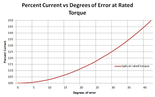
Figure 2: Percent current vs degrees (electrical) of error at rated torque.
Iqds is the total stator or phase current of the motor. As the degree (electrical) of error in the commutation angle increases, the motor has to draw more current to generate the required torque. As this figure demonstrates, it is essential that the position of the encoder on the motor shaft does not change to maintain proper stator field commutation.
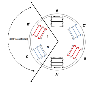
Figure 3: Six pole motor stator showing 360° (electrical) between north and south pole pairs corresponding to 360° / 6 poles = 120° mechanically.
Encoder shaft position and precision
360 degrees electrical corresponds to one cycle of the AC voltage waveform of a given frequency. Applied to the motor stator windings, this translates to a north electromagnetic pole during the positive half cycle and a south electromagnetic pole during the negative half cycle. Thus, 360 degrees electrical on the stator corresponds to a north-south pair of motor poles, as seen in Figure 3. To determine the relationship between mechanical degrees and electrical degrees, Equation 1 can be used:
As the number of motor poles increases, the mechanical degrees the rotor must rotate for 360 electrical degrees decreases. For example, a 6-pole motor would have 120 mechanical degrees between pole pairs whereas a 20-pole motor would have 36 mechanical degrees between pole pairs.
The encoder’s electrical position can be expressed in a range of counts which corresponds to 0 – 360° electrical degrees. While the electrical position can be used to relate to the active commutation angle for motor rotation, it is most commonly referred to as a static position offset (e.g. relative to one of the motor poles). For the purpose of this article, a 16-bit resolution of encoder electrical position counts between pole pairs is considered; in this case, the encoder electrical position between pole pairs would correspond to a range of 0 – 65,535 counts. The relationship between counts and mechanical degrees can then be expressed as:
OR
As the number of motor poles increases, the number of counts per mechanical degree increases; that is, the degree of mechanical error translates to the corresponding degree in electrical error and increases as the number of motor poles increase. This makes the mechanical alignment of the encoder much more critical for proper operation. This can be highlighted by continuing the previous example; a 6-pole motor would have 546 counts per mechanical degree whereas a 20-pole motor would have 1,820 counts per mechanical degree.
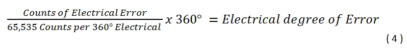
For PM motors, torque can be maximized when the stator and rotor magnetic fields are 90° apart from each other. The electrical degree of error will therefore dictate the maximum torque for a given current supplied to the motor. The electrical degree of error is shown by Equation 4 and the percentage of maximum torque for a given electrical error is shown by Equation 5:

This maximum torque will occur within a window of approximately 4,000 counts (+/- 2,000 counts). An error of 2,000 counts corresponds to an error of 11° electrical on the stator magnetic field sine wave commutation angle from Equation 6:
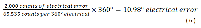
An error of 10.98° electrical in the stator field commutation angle means that there is only a 1.83% error in torque. See Equation 7 below:
But, as was shown in Figure 2, there is a non-linear relationship between the electrical degree of error (due to mechanical degree of error) and the current (and therefore torque, since this is linearly related with the current for PM motors) due to the sine function in Equation 5.
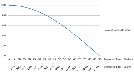
Figure 4: Percentage of Maximum Nominal Torque for a given degree of error in electrical degrees and counts.
Further continuing the previous examples to exemplify this, 1° of mechanical mounting error of the encoder on the motor shaft for a 20 pole motor translates 1,820 counts of electrical error which results in 1.52% loss of motor torque for a given current, whereas 2° of mechanical mounting on the same motor equates to 6.0% loss of motor torque and 3° error a 13.4% loss of motor torque and so on. It’s not difficult to see how the encoder mounting becomes critical and must remain precise without slippage. Even for a very large 2” diameter encoder shaft with a circumference (π x diameter) of 6.28”, 3° of mechanical error corresponds to about 1/128” of movement on the outer diameter. If the encoder is ever removed, an encoder position offset learn procedure will need to be performed again.
The following section contains a few reasons why the position of the encoder on the motor shaft may have changed. Part I issues focus on a car that had previously been running trouble-free, while Part II focuses on issues encountered during the startup and commissioning phase.
Part I: Encoder Issues with a Previously Running Car
Encoder Slippage Due to Poor Mounting/Loose Connection
Encoder slippage can occur when the position of the encoder on the motor shaft changes over time, in different hoistway positions, or in different directions. This could be due to poor or improper mounting, grease on the mounting shaft, broken mounting tab, or catching. To ensure the encoder is not slipping, after the initial encoder position offset learn, the car can be run to the bottom of the hoistway and another encoder position offset learn can be completed. Then, the car can be run to the top of the hoistway and a final encoder position offset learn can be completed. These three encoder position offset learn values can then be compared against each other. If the rotor position changes drastically (≥±2,000 counts) between these three encoder position offset learn procedures, this is most likely due to the change in physical relationship between the encoder and motor shaft. In some rare cases, slippage can occur between the motor shaft and rotor steel laminations (e.g. loose fit, broken weld, etc.). The degree of encoder slippage may not be visually detectable.
Ensure the motor shaft is clear of dirt and debris that could cause mounting problems. Verify all set screws are tight and the encoder is mounted squarely on the motor shaft. Some encoders have a screw that fits inside of the end of the motor shaft rather than relying on a set screw for mounting. If the screw used to mount the encoder is too long, it may bottom out on the motor shaft threads resulting in a poor/loose connection. Figures 5 – 8, below, show examples of encoder slippage and mounting problems.
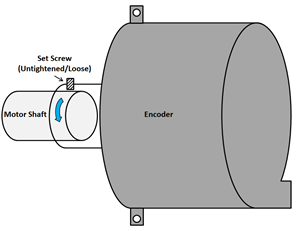
Figure 5: Encoder not secured properly to motor shaft due to an untightened or loose set screw may result in slipping.
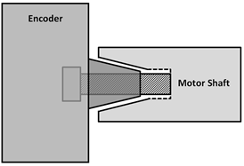
Figure 6: Mounting screw is bottomed out on motor shaft causing a poor connection may result in slipping.
Part II: Encoder Issues during Startup
Incorrect Encoder Channel Phasing
After an encoder offset position learn has been performed, if the motor does not turn and draws a high current, then the encoder phasing may need to be changed (e.g., Not Inverted to A-B Swapped). Depending on the mounting orientation of the encoder and phasing of the motor, the incremental A-B speed channel phasing may need to be swapped. Depending on the VFD, the channels may be swapped via a software parameter setting.
After an encoder offset position learn has been performed, if the motor runs without drawing high current, but runs in the wrong direction, in both the up and down directions, then only the direction of rotation needs to be changed (e.g., Not Inverted to Inverted Rotation).
*Each channel phase pair will have a corresponding encoder position value. If changing the encoder channel phasing by swapping A-B phasing, or vice versa, a new encoder position offset learn procedure must be completed.
*See Incorrect Motor Phasing and Encoder Mounting section for more information.
Incorrect Motor Data
If the rotor position is changing drastically (≥±2,000 counts) between encoder position offset learn procedures, the sheave is not moving, and encoder mounting has been verified, the motor data entered into the drive may be incorrect. Equation 8 holds true for all PM (synchronous) AC motors and should be verified against nameplate motor data:
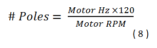
Some motor manufacturers may de-rate motor data depending on the application. De-rated motor data must be scaled properly so that the number of motor poles remains constant. Using motor data from Figure 9, a motor that is originally meant to run at 200ft/min. can be used to run in an application at 100ft/min. by reducing the speed and frequency by a factor of two. It is important that BOTH the frequency and speed are scaled by the same factor to ensure pole count consistency.
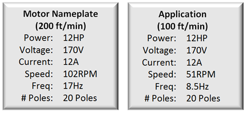
Figure 9: Motor and application data scaled for 200 ft/min and 100 ft/min respectively.
*The number of motor poles will always be an EVEN, WHOLE NUMBER.
Incorrect Motor Phasing and Encoder Mounting
In three-phase AC motor applications, the UVW motor phasing determines the direction of rotation. If the motor turns in the wrong direction, two phases can be swapped to switch the direction. In open-loop induction motor applications without an encoder, this does not present a problem. However, when an absolute encoder is used, proper motor phasing impacts the A-B channel phasing of the encoder.
The UVW phasing of the motor and A-B phasing of the encoder are related such that the encoder has an established convention for incrementing and decrementing position values coinciding with the direction of the motor stator field. This convention is typically indicated by the encoder manufacturer with a diagram similar to Figure 10 below.
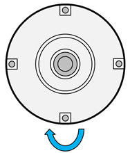
Figure 10: Direction of shaft rotation for output position value signals.
The position values will increment or decrement according to the manufactures established convention. When the encoder position values are incrementing or decrementing in the wrong direction, this can cause the motor to draw a high current or not turn.
The A-B channel feedback from the encoder determines if the position values are incrementing or decrementing. Absolute encoders typically feature incremental speed channels consisting of sine and cosine waves with an amplitude of 1Vpp, phase-shifted by 90° for the A and B channels respectively as seen in Figure 11.
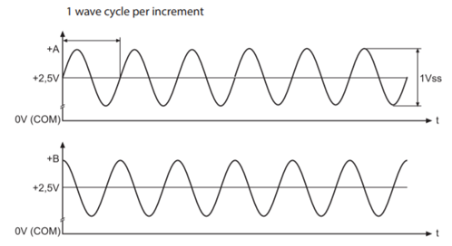
Figure 11: Sine and cosine speed feedback signal.
Depending on the A-B phasing of the encoder and the established position incrementing and decrementing convention, channel A may ‘lead’ or ‘lag’ channel B.
The position value convention also applies to the physical mounting of the encoder on the motor shaft. Depending on motor type and encoder type, the encoder may be mounted on either side of the motor (stub shaft, etc.) or have an adjustable mounting configuration on the motor shaft. This will cause a discrepancy in the position value incrementing and decrementing convention. It is recommended practice to phase the drive and motor together such that U-U, V-V, and W-W and adjust the A-B phasing as needed. The A-B channels of the encoder may be swapped physically at the interface or with a software parameter setting based on the drive type.
Conclusion
Due to their design, PM motors require rotor position in relation to a stator pole pair to be known by the VFD. Proper encoder mounting, alignment, channel phasing, and motor data/phasing are essential for maximum torque output and trouble-free operation. Encoder problems such as slippage can be difficult to diagnose since it may happen gradually over time or not be visible to the user. However, troubleshooting using the above steps can quickly identify encoder problems.
If you have questions about how encoder positioning can affect your elevator’s VFD, drop us a line using the Contact Us form.
Related Articles
Let's Work Together
Connect with us today to learn more about our industrial automation solutions—and how to commission them for your application.