
How a multi-axis auxiliary inverter solution can benefit your EV design
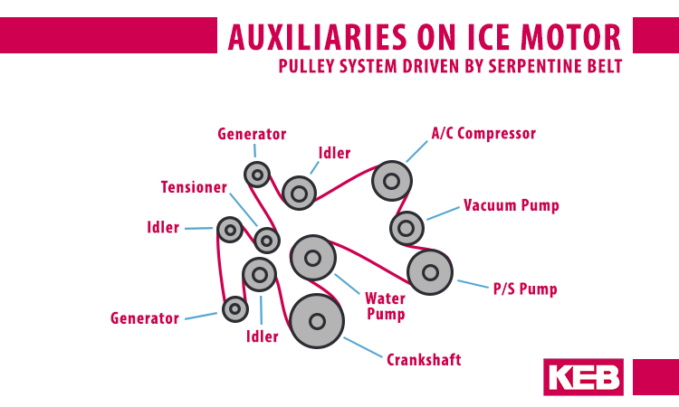
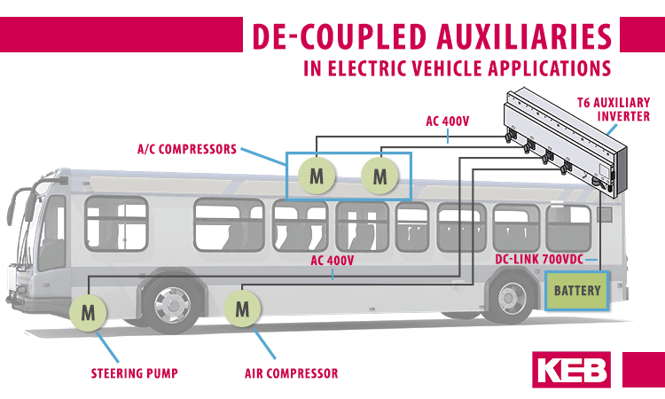
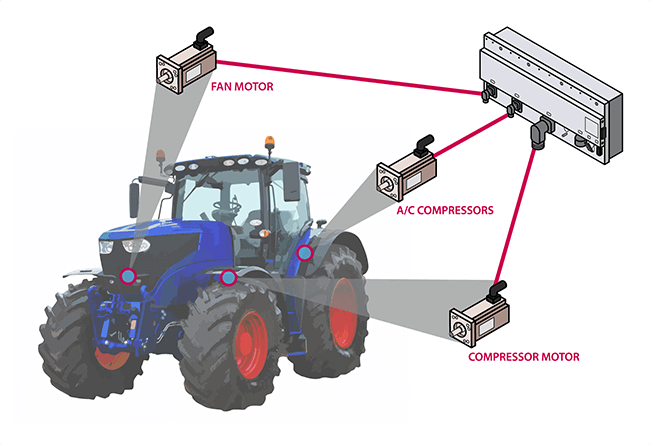
When it comes to electrifying vehicles, there are several components that become de-coupled from being driven by the engine such as air compressors, steering pumps, and air conditioning compressors. In this case, each component can be operated independently with its own auxiliary electric motor.
Likewise, each auxiliary motor can be controlled by its own inverter, or variable frequency drive, based on the needs for on-demand performance as well as optimal operational efficiency. This, of course, requires multiple VFDs and begs the question of which inverter layout or topology is the most beneficial for the vehicle design.
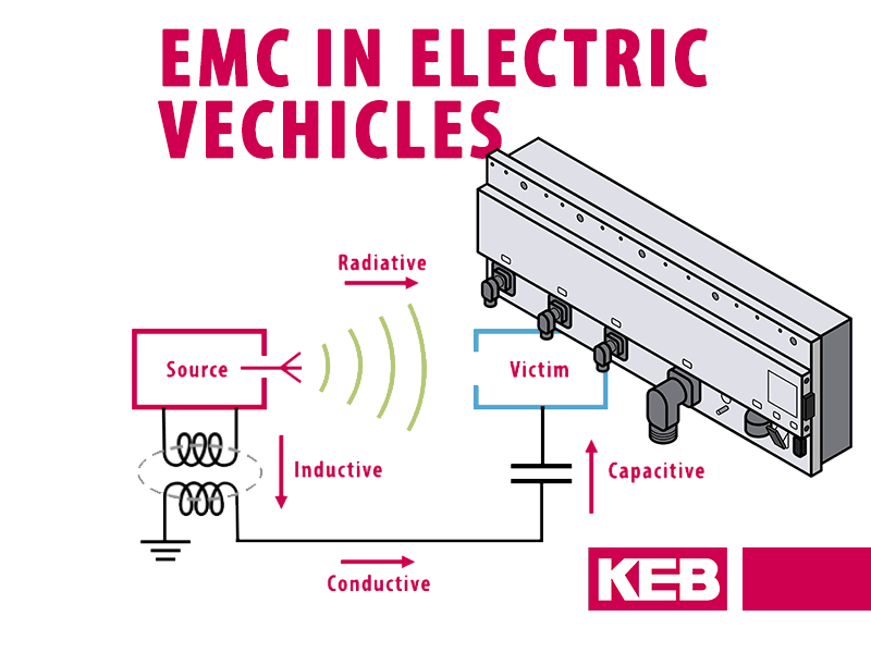
Several considerations for electrifying the auxiliary axes include cost, space constraints, and power requirements. But, while it is easiest to compare offerings on an apples-to-apples basis, the comparison should be made on a broader, system basis; that is, to include all additional required components such as fuses, DC cabling, cooling systems, and CAN bus control. Eliminating such components can decrease system cost and reduce complexity as well as mitigate other potential headaches such as electromagnetic interference (EMI) and CAN-bus communication issues.
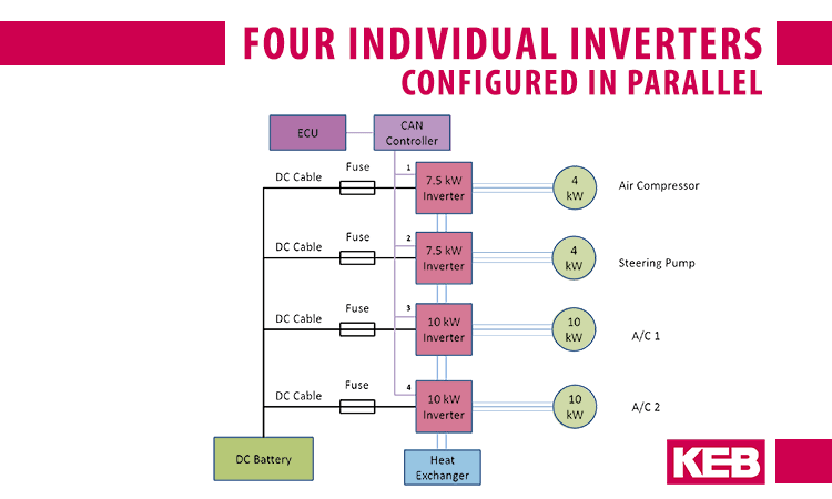
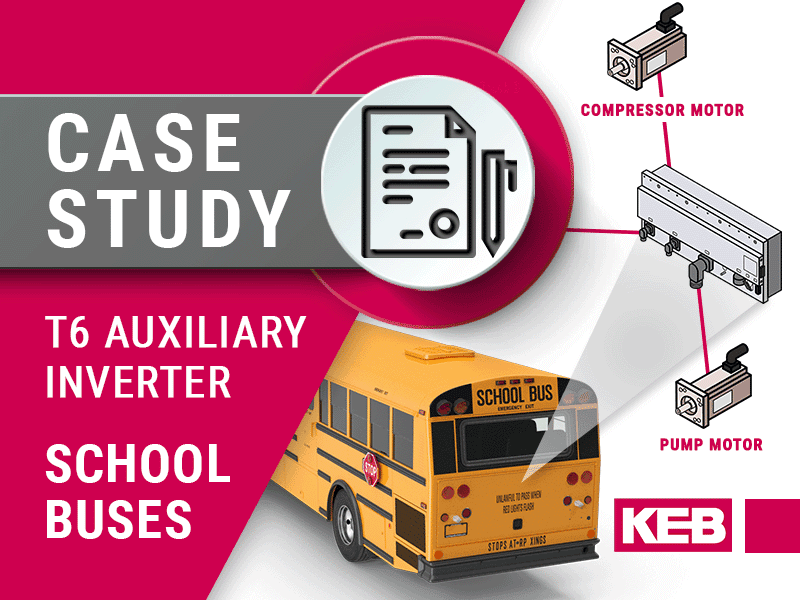
As an example, let’s consider a transit bus application that has an air compressor (4kW), a steering pump (4kW), and two air conditioner compressors (10 kW each).
Solution 1 – Four Separate Inverters
The first solution for an EV Inverter design consists of four individual drives configured in parallel.
Due to the parallel layout, each inverter requires its’ own DC supply cable, fusing, CAN node ID, and heat exchange connection. While the benefit of such a system is that it is modular and can be distributed especially throughout the vehicle, there are several drawbacks.
One drawback is the redundancy of components, including DC bus cabling, inverter fusing, CAN-bus connections, and heat exchange connections. This redundancy not only contributes to system cost but also adds to the complexity of the system layout.
A second drawback is the potential for serial-bus communication problems due to EMI from DC wiring.
A third drawback is the programming complexity and potential serial communication bus loading from independent node IDs.
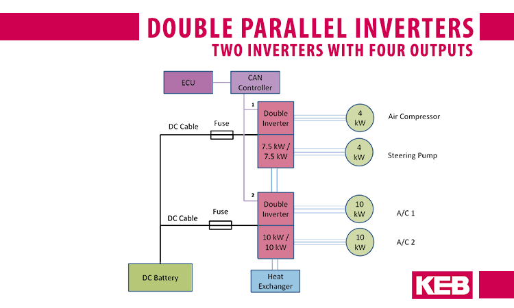
Solution 2 – Parallel double inverters
While a solution with double inverters begins to address the drawbacks of a distributed system where all units are independently housed, double inverters may have limitations to the sizing combinations available or whether a unit has different power stage outputs. The application example shows one double inverter with two 7.5kW outputs and one double inverter with two 10kW outputs. Other applications may require other output combinations such as one 30kW output and one 7.5kW output. The question is whether the needed combination is available without having to unnecessarily oversize an output based on available combination offerings or a unit in parallel.
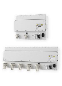
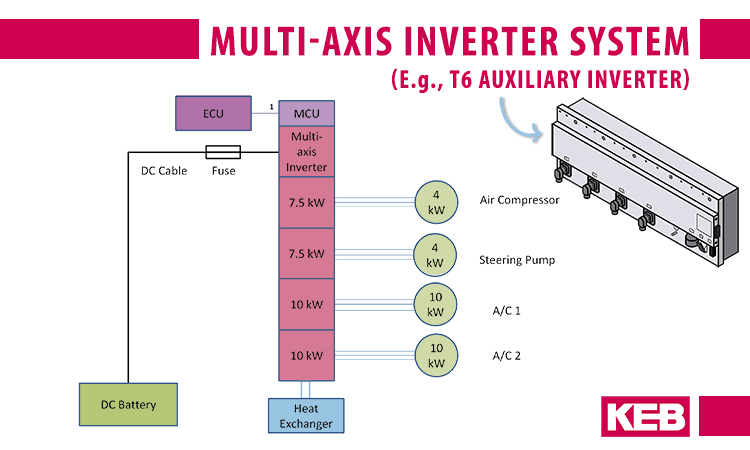
Solution 3 – Multi-Axis Inverter
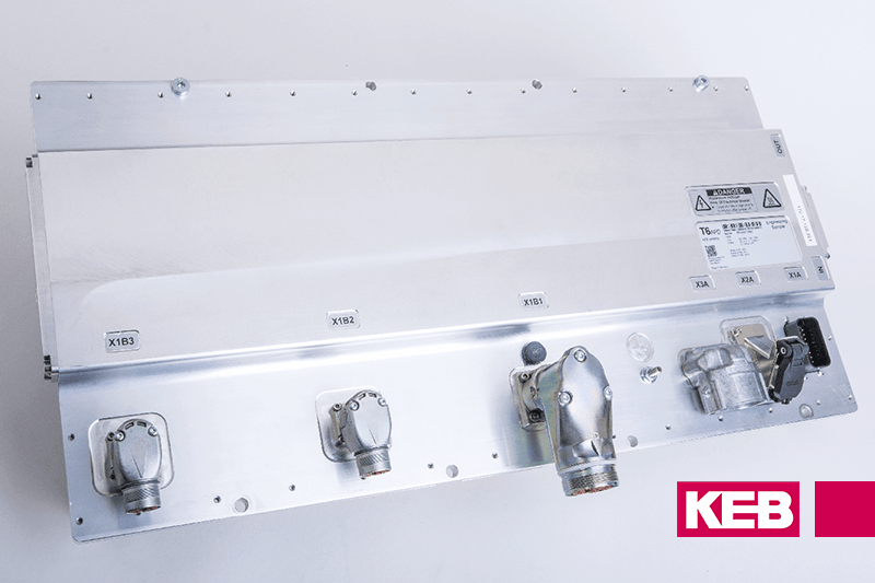
The third solution consists of a multi-axis inverter system (with an embedded controller).
Lastly, the option of a multi-axis inverter which is scalable in the number of outputs reduces redundancy of external components to reduce system cost and connection complexity as well as eliminates internal redundancies such that the marginal cost of additional motor outputs decreases.
Multi-axis auxiliary inverters become attractive when controlling more than two auxiliary motors. They get increasingly attractive as more auxiliary axes are added.
Additionally, modular power stage outputs can be matched to the exact requirements of the application preventing unnecessary oversizing or the need for parallel units. Lastly, consolidation also allows for a deeper level of system integration. One example is internal DC choke filters to mitigate EMI to allow for reliable system operation. Another example is an embedded application controller which can operate independently or in parallel with the vehicle’s electronic control unit (ECU) to reduce serial communication bus loading. This also allows for system coordination between inverter outputs such as load balancing for prioritization and energy management.
When comparing each EV inverter design for electrifying auxiliaries, it is worth considering the offerings in the context of a system, particularly the system layout and topology when multiple inverters are required. Comparing units side-by-side on cost alone ignores external components which add to the system cost, as well as the benefits of a consolidated solution that reduces complexity (which can be the source of other problems, such as EMI) and allows for further benefits of an integrated system solution. This is especially true as the number of auxiliaries within a vehicle increases.
“Comparing units side-by-side on cost alone ignores external components which add to the system cost, as well as the benefits of a consolidated solution…”
Related Articles
Let's Work Together
Connect with us today to learn more about our industrial automation solutions—and how to commission them for your application.