
Grounding and Power Cable Guidelines for High Speed VFD Applications
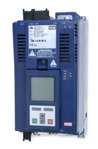
High speed motors, whether they be permanent magnet synchronous, induction or synchronous reluctance, provide a high efficiency, high power density motor that is being increasingly utilized in applications such as wastewater treatment blowers, industrial chiller compressors or industrial heat pumps. In order to reliably and efficiently operate these motors, a VFD designed for the required high frequency output is needed. When running motors at these high speeds, the output frequency of the VFD can reach values of 1600 Hz or more. KEB is a world leader in solving applications utilizing high speed motors. The KEB high speed VFD line is a reliable, proven system that ensures the best performance of the high speed application.
Download the Whitepaper: Grounding and Power Cable Guidelines for VFD Applications
When running a VFD at high frequency output, to minimize the current and voltage harmonics in the motor windings, it is best to run the system at a high switching frequency.
Read More: VFD Switching Frequency
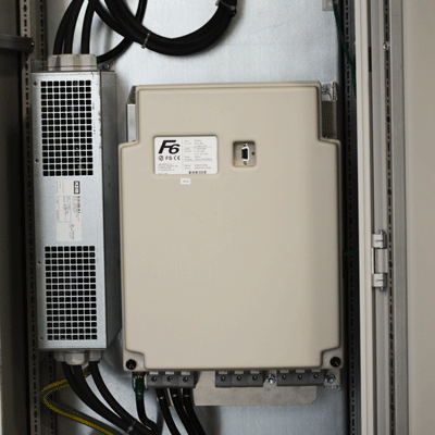
The KEB high speed VFD is designed to operate at switching frequencies up to 16 kHz. In addition to the higher switching frequency, KEB also developed a line of sine filters, specifically designed for high speed applications, to further filter out excess harmonics to provide a clean sine wave voltage and current to the motor.
Considerations for Designing Grounding and Power Cables
To get the best performance out of the system, many considerations must be taken into account when designing the powers transmission components for the high speed system. For this article, we will discuss a few highly critical components: grounding and power cables.
High speed applications present some challenges that may not appear when running motors at standard output frequencies (60 Hz, for example). The higher frequency output required for the high speed applications requires the VFD to run at a high switching frequency (8 kHz or 16 kHz). The higher switching frequency combined with the typically low inductance of high speed motors, introduces high frequency current harmonics to the cabling in the system. If these high frequency current harmonics are not mitigated properly, the system could experience nuisance trips or potential component damage.
As the AC current frequency increases, the skin depth of the conductor decreases. The skin depth of the conductor refers to the usable area where the current may flow. A changing AC current in one conductor can create a current in a parallel wire. The same effect occurs within an individual conductor. The changing fields within the conductor create opposing eddy currents which can cancel out parts of the main current flow.
The eddy currents can be looked at as a neutral circle current that starts at the very center of the conductor where no current can flow. At low frequencies (e.g. 60 Hz), the neutral circle current is virtually non-existent. As the frequency increases, this neutral circle current grows, effectively reducing the amount of area of the conductor that can carry current. As the frequency of the current waveform increases, the current effectively flows on the surface area of the conductor. The reduction in available current flow area due to the high frequency current would increase the effective resistance of the conductor. The effective increase in resistance reduces the cables capacity to conduct the high frequency current which could result in higher cable heating or potentially a reduction in system power capacity. Thus, for high frequency applications, using a conductor with as high a surface area as possible is required.
Grounding Solutions
For a ground connection, if the skin effect of the conductor is such that the effective area available to carry the current harmonics is not sufficient, the excess current harmonics may find another path. This may be to the control circuitry of the VFD or through the motor bearing housing. Both of these options could cause operation issues with the system, causing unnecessary downtime and/or breakdowns of mechanical components.
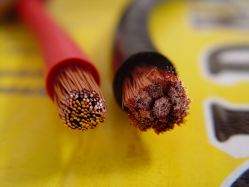
When designing a high speed VFD system, KEB recommends using a high stranded cable for any connection that will be subject to the high frequency currents. The high stranded cables utilize many small strands within the cable cross section. Each individual strand still experiences the skin effect described above, but the increased number of strands in the high stranded cable increases the total surface area of the conductor as compared to standard stranded or solid conductor.
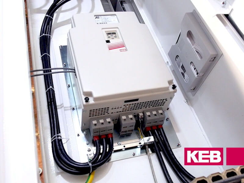
Electrical Enclosure Layout
When designing the electrical enclosure layout, KEB recommends that the VFD be mounted on an unpainted, zinc plated back panel. The zinc plated back panel becomes the main high frequency ground point and provides a large surface area for the high frequency current harmonics to be shunted to the main building ground.
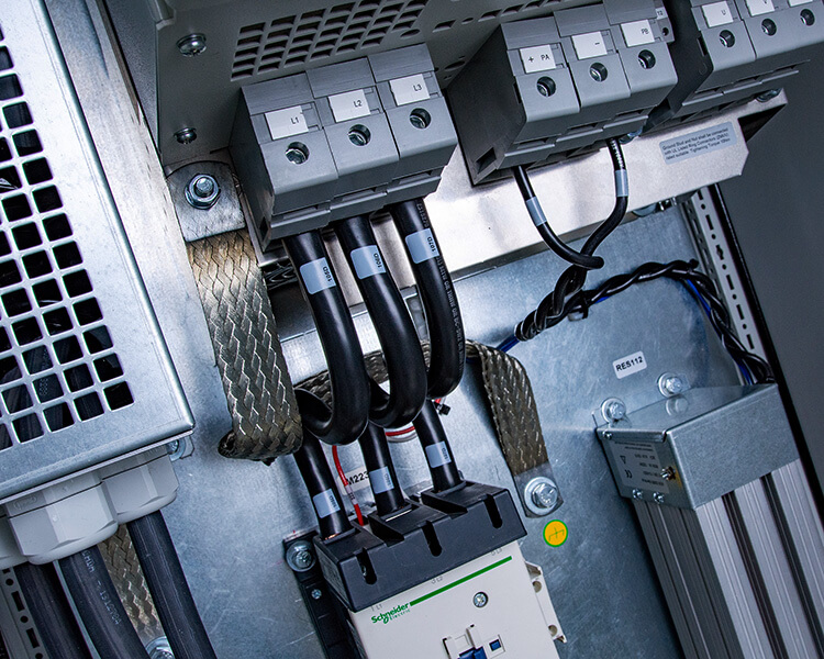
Figure 1 below gives a graphical description of the type and size of cable recommended by KEB for high speed applications. The cable size is dependent on the application requirements. Please consult a KEB Engineer for more information.

KEB recommends using UL1283 or UL1284, high strand count cable for the ground connection from the motor directly to the KEB VFD. The direct connection using the high strand count cable provides the lowest impedance path for the high frequency current harmonics to be shunted back to the main high frequency ground point.
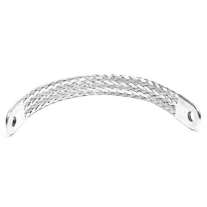
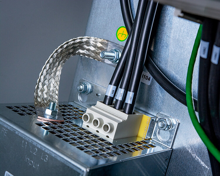
Since the zinc plated back panel is used as the main high frequency ground point, KEB recommends that any component which may have a high frequency component should be bonded to the back panel using a braided ground strap. This braided ground strap provides a low impedance path to the back panel for any high frequency current harmonics that are conducted back to the VFD or high frequency input filter (EMI), if applicable.
KEB recommends using UL1283 or UL1284, high strand count cable for motor cable from the VFD to the sine filter and from the sine filter to the motor. Any cables that exit the enclosure to the motor should be shielded or in a metal conduit. The shield or conduit should be connected directly to the main ground lug of the VFD.
For main power connections that are not high frequency, KEB recommends UL1283 or UL1284, regular strand count cable.
Contact KEB to discuss your high speed VFD application or our noise filtering solutions.
Related Articles
Let's Work Together
Connect with us today to learn more about our industrial automation solutions—and how to commission them for your application.