
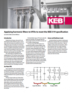
The input stage of a Variable Frequency Drive (VFD) often generates undesirable harmonic distortion, but this issue can be mitigated effectively by implementing a harmonic filter. This article overviews VFDs, how the VFD input stage creates harmonic distortion, the negative effects of harmonics, and how harmonic filters reduce these harmonics in industrial applications.
VFD Basics
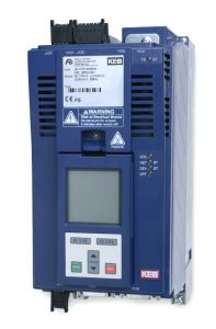
Variable frequency drives (VFDs) used in industrial applications provide many benefits, including energy savings, better process control, extended component lifetime, and increased machine safety when utilizing functional safety features.
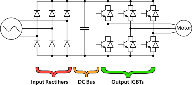
Variable frequency drives consist of three sub-systems: the diode bridge converter, DC bus, and IGBT output inverter.
The diode bridge input rectifier typically consists of a full-wave 6-pulse rectifier, which rectifies the incoming AC voltage into a DC voltage. The DC bus system utilizes DC capacitors to help smooth the rectified AC voltage and provide voltage storage for the system.
Finally, the IGBT output system utilizes the DC bus voltage and creates the variable frequency and voltage output to the motor, using a pulse width modulated (PWM) control.
Any VFD which uses a 6-pulse rectifier on the input stage may be one source of current and voltage harmonics on the mainline. (Other sources of mainline harmonics include: Arc furnaces, any power supply using a static power converter, or inverters for distributed generation.) This is due to the non-linear load produced by the 6-pulse rectifier.
A load connected to an AC input voltage is a linear load if the current draw is in the same form as the voltage (resistive, inductor, or capacitive load, for example). A non-linear load draws a current that is not in the same form as the AC voltage waveform – non-sinusoidal.
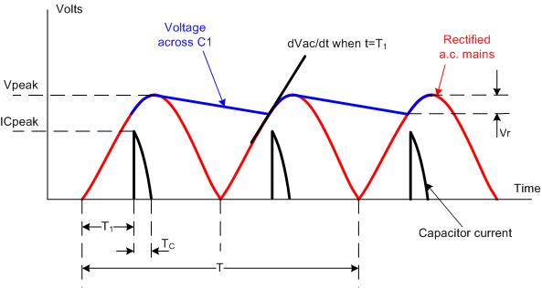
In the VFD system, once the DC bus capacitors are charged, the input current to the capacitors will flow only when the incoming AC voltage is greater than the DC bus voltage. This is near the top of the arc of the sine wave voltage waveform.
As the voltage of the sine wave drops below the DC bus level, the current will stop flowing as shown in the diagram below. This nonlinear capacitor current results in a current pulse on the main incoming voltage line.
What Causes Harmonic Distortion in VFD?
VFDs create harmonic distortion. Because VFDs cause harmonic distortion, a harmonic filter for VFDs reduces harmonics.
In other words, any VFD using a bridge rectifier inherently draws harmonic current from the utility. The harmonic current draw causes voltage distortion on the mains that can create power quality issues for other electrical loads.
Electrical loads like resistors and line-fed induction motors draw a sinusoidal current from the supply. Most commercial VFDs use a 6-pulse bridge rectifier to convert from AC to DC power. 6-Pulse inverters draw a non-sinusoidal input current which then creates distortion on the supply voltage.
The voltage distortion is undesirable because it can negatively affect the operation of other electrical loads. Critical applications using VFDs like wastewater treatment plants, elevators, and airports might need to mitigate harmonic distortion.
Negative Effects of VFD-Caused Harmonics
Harmonics on the mainline can have the following effects:
- Cause interference with communication circuits
- Transformer overheating
- Nuisance circuit breaker trip
- Neutral overloading
- Capacitor bank failure
How much harmonic content on the mainline is too much?
To assist with this question, the Institute of Electrical and Electronics Engineers (IEEE) developed a standard for harmonic levels. The current standard for acceptable harmonic content is IEEE519-2014.
The main components of this standard define the acceptable levels of current and voltage harmonics based on the short circuit current rating (SCCR) of the incoming power distribution system. The amount of distortion a system can tolerate depends on the input impedance level of the voltage distribution system.
The standard considers the distribution system impedance by determining acceptable harmonic levels based on the system SCCR. Lower impedance or stiffer distribution networks can tolerate a higher level of harmonics. Where higher impedance or softer distribution networks can tolerate a lower level of harmonic content.
The IEEE519-2014 standard also defines the point of common coupling (PCC) where the harmonic levels are to be measured. This provides a standard measurement location for the harmonic content of the facility to be measured.
Since most industrial environments consist of linear and non-linear loads, the overall effect at the PCC may be negligible even if an individual system produces some harmonic content. The IEEE519-2014 standard provides some clarification on the PCC over earlier versions of the standard:
…the PCC is usually taken as the point in the power system closest to the user where the system owner or operator could offer service to another user. Frequently for service to industrial users (i.e., manufacturing plants) via a dedicated service transformer, the PCC is at the HV side of the transformer. For commercial users (office parks, shopping malls, etc.) supplied through a common service transformer, the PCC is commonly at the LV side of the service transformer.
The IEEE519-2014 standard provides guidelines for the allowable harmonic content on a voltage distribution system. Standards are provided for both voltage and current harmonic levels.
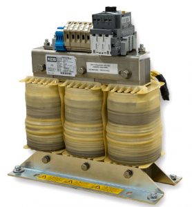
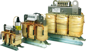
KEB Z1 Harmonic Filters
There are several ways to address harmonics, but harmonic filters balance performance and cost.
KEB’s Z1 (zee-one) Harmonic Filters are designed to meet IEEE (eye-triple-E) 519 (five-nineteen) harmonic levels. The filters are offered in graduated sizes up to 400Hp.
To achieve the best possible performance, KEB offers filters for different electrical mains around the globe. Filters are available for both 230V and 480Vac mains. Additionally, some filters are optimized for both 50Hz and 60Hz mains.
KEB Harmonic Filters are used to limit and control VFD distortion. Using a harmonic filter with a VFD reduces the amount of harmonic current. Therefore, the voltage distortion on the mains is reduced.
Reducing VFD Distortion for Industrial Applications
KEB Harmonic Filters are intended for demanding industrial VFD applications and feature a 150% current overload rating for 60 seconds. The units feature overload protection and temperature sensors for the filter windings as standard.
The Z1 filters are 99% efficient at full load. This is achieved through the use of high-quality steel laminations and winding configuration.
KEB’s Z1 filters also feature high-performance 3-phase capacitors for increased operating lifetime and reliability. The harmonic filters use a compact design and flexible mounting concept.
Because the capacitor bank can be mounted separately from the core – up to 2 meters apart, a machine builder can easily position and mount the components inside an enclosure. As an option, we offer large filters in a pre-wired NEMA1 enclosure.
KEB Harmonic Filters are UL listed and carry a CE mark to ensure the highest quality and performance. This makes them well-suited for even the most demanding industrial applications.
KEB – Your Harmonic Filter Technology Partner
As an automation and control technology leader, KEB can support your needs with flexible solutions for reducing VFD distortion.
Download the white paper for more details on applying harmonic filters to VFDs to meet the IEEE 519 specification.
Want to know more about harmonic distortion and how to address it? Contact a KEB America engineer to discuss your application.
Related Articles
Let's Work Together
Connect with us today to learn more about our industrial automation solutions—and how to commission them for your application.