
The purpose of this article is to demonstrate how bits, hexes, bytes, and words are used to build a system of PDO (Process Data Object) mapping for digital fieldbus communication.
What is PDO Mapping?
PDO mapping is made up of several predefined binary codes that describe the sequence and length of the mapped application objects that are transmitted in a single Process Data Object. If this sentence is too much to handle, let’s break it down into smaller segments.
Basics of Binary Communication
Binary is used in fieldbus communication to send complex information in a compact, easily understood data packages. Using EtherCAT communication as an example, we will go through the basics of data mapping, the foundation of digital fieldbus communication in order to help you plan your PLC and VFD programming more effectively and know how the bits and status words work in digital communication protocols like EtherCAT.
Related Article: Basics of Digital Data Types
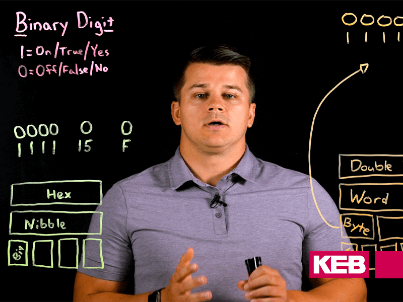
As explained in a previous blog post, every type of digital communication comes down to the concepts of 1s and 0s (on and off) to build increasingly complex packages of information. The video below goes through these basic concepts that make up our modern, interconnected, digital world today.
Understanding Bit Coding in Fieldbus Communication
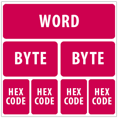
Bit coding, also known as bit mapping, assigns specific things to specific bits. For example, CiA 402 Control Word used in KEB’s generation 6 drives is one Word (16 bits/2 bytes).
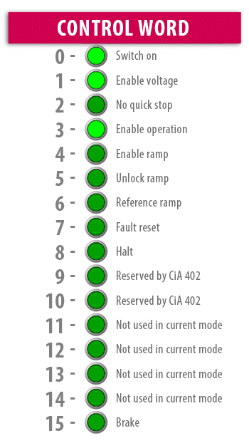
Each bit in a Control Word is allocated to a specific action. The bits start with 0 and go up to 15. For anything to happen in regards to VFD operation certain bits must be switched on/true. In order for the VFD to start operation, bits 0, 1, and 3 must be true/on as in the image above (see Figure 2). If these are not designated as true/on then nothing will be permitted to begin or change within that VFD.
To give you another example of how these Control Words are assigned inside a PLC programming software, such as KEB’s COMBIVIS 6, you can add certain PDO (process data objects) into the control word that is sent to the VFD each EtherCAT cycle.
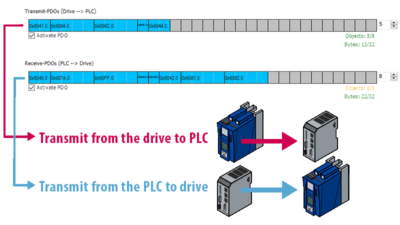
Process data objects are easily mapped in the COMBIVIS 6 wizard (Figure 3). Each object, or parameter, has a specific data length. Control Word is 2 bytes/16 bits. KEB’s Gen 6 drives support up to 8 objects and 32 bytes, which equal 16 words, or 256 bits, with a minimum 400µs cycle time.
Conclusion
Bits can be mapped to pack a lot of info into a small data size that is easily understandable. These bit-coded parameters (as well as standard numeric valued parameters) can then be mapped as PDO to achieve synchronous digital fieldbus communication.
If you’d like to learn more about fieldbus communication types, or if you want to solve for an automation application you are currently working on, Contact a KEB application engineer today.
Related Articles

Let's Work Together
Connect with us today to learn more about our industrial automation solutions—and how to commission them for your application.