
How Does Closed Loop Control Work in a VFD?
In our latest YouTube videos, we discuss how adding encoder feedback allows the drive to more precisely control the speed and torque of the motor. In this article we’ll talk about the more advanced Closed Loop control for precise control of the motor’s speed and torque.
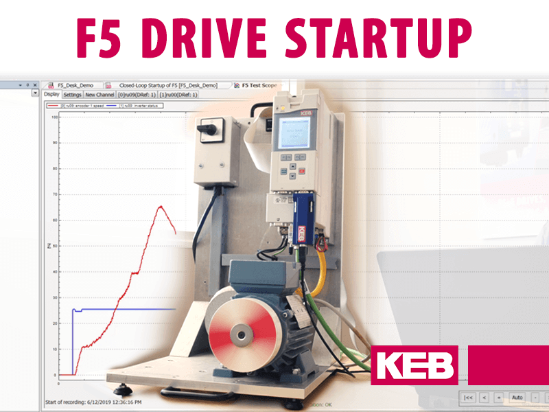
Watch the video below as Mike walks you through the concepts of closed loop VFD control.
V/Hz Open Loop Control
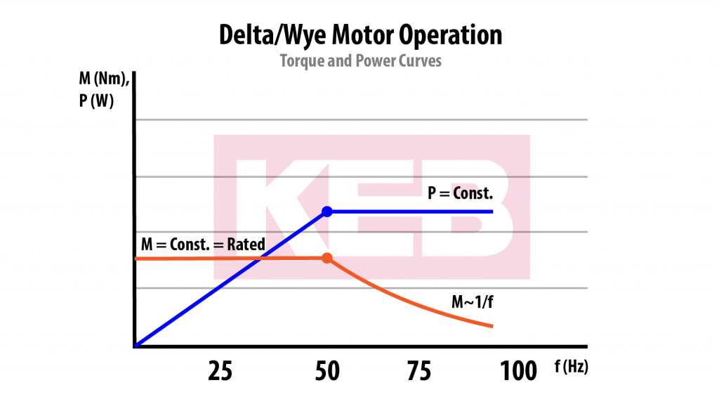
Using open loop control with a VFD is an effective and low cost way to control a motor. In an induction motor, if the ratio of supply voltage and frequency is constant the magnetic flux and thus also the motor’s torque will be constant. This is perfect for applications such as pumps, fans, or conveyors. In these operations the speed may need to occasionally change, but the load is mostly constant. For applications with more precise speed and torque requirements, a more advanced type of control is necessary.
Encoder Feedback
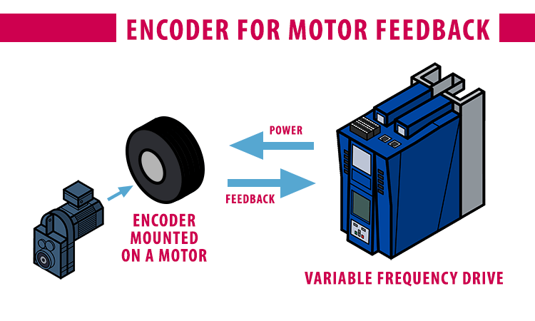
With open loop control a drive constantly outputs power to the motor, but it has no way to actually tell if everything is operating correctly at the motor. By adding an encoder to the motor and providing that feedback to the drive, it can know at precisely what speed the motor is running. This can then be incorporated in the drive’s closed loop control algorithm for precise control of the speed and torque.
Closed Loop Block Diagram
In closed loop control, the drive uses the encoder feedback in its control algorithm to know exactly what to output to the motor to run at the desired speed and torque.
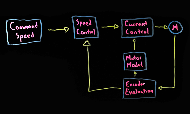
- First, motor information goes through the encoder evaluation. One example of an encoder adjustment is if the encoder is placed on the output of a gearbox instead of on the motor shaft. In this case the measured speed would be different than the actual motor speed and the drive can adjust to the gear ratio.
- Once evaluated and adjusted if necessary, the speed is fed into the speed controller and motor model.
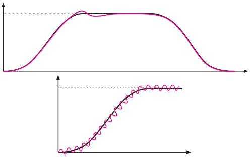
- With changes to the motor’s command speed or load, the actual speed will not perfectly match the command. The speed controller constantly monitors this error and uses PI (Proportional and Integral) control to adjust its output to try to eliminate the error.
- The motor model uses the motor’s basic nameplate data and KEB’s motor identification process to create an electronic equivalent of the motor. During the motor identification, current is pushed through the motor at various frequencies to measure the motor’s stator resistance, inductance, etc. Then using this electronic equivalent of the motor and the actual measured output voltage and current, the motor model calculates at what speed the motor should be running.
Conclusion
Using the feedback from the motor and the drive’s complex control algorithm, closed loop control allows for highly dynamic and efficient performance across the motor’s full speed range. If you like our videos please like and subscribe to stay up to date on everything going on at KEB America. And keep an eye out for our next video on the basics of induction motors.
Related Articles

Let's Work Together
Connect with us today to learn more about our industrial automation solutions—and how to commission them for your application.