
How VFD harmonics relate to elevator applications

In my previous post about harmonics, I covered a few of the questions we frequently get. This post will explain how this information relates to elevator drives.
When referring to VFDs and individual energy consumers, why is current distortion more applicable than voltage distortion?
The harmonic voltage distortion on a system is affected by all operating loads on the utility. Unless all other electrical loads are turned off when the voltage measurement is taken, it is practically impossible to use this measurement to isolate the distortion effects caused by an individual VFD load.
A more relevant measurement for an individual user or component manufacturer is a current measurement. A harmonic current distortion measurement taken at the equipment disconnect isolates the drive’s individual harmonic performance. In theory, if the power quality of the individual load is in compliance with the desired utility distortion levels, then it could not cause the utility to fall out of compliance.
With this in mind, the IEEE 519 standard defines acceptable THDI levels to be taken at a point of common coupling (PCC). The exact location of the PCC is open to interpretation and needs to be selected for each application. In practice, the PCC is usually taken to be the disconnect switch supplying the elevator control room.
What is Power Factor (PF) and how does it related to harmonics?
Power factor (PF) is sometimes used to refer to the amount of harmonics in a system. The total PF represents the ratio between the power being put into useful work (active power) at the fundamental frequency and the total electrical power being transferred. A unity PF (1.00) is ideal and indicates that all power being delivered is being usefully consumed by the load. A low power factor is to be avoided because it requires electrical components to be oversized to accommodate the transfer of unused reactive and/or harmonic power.
The IEEE 519 standard describes two components that make up the total power factor – the displacement factor and the distortion factor.
PFTotal = PFDisplacement * PFDistortion
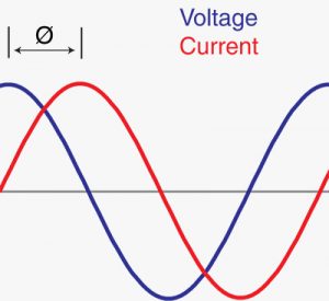
The PFDisplacement is the ratio of the used active power (measured in watts) and the reactive power (measured in VoltAmps) at the fundamental frequency. The displacement factor is affected by the impedance of the load and calculated by measuring the phase shift (expressed as ø) between the applied voltage and load current. A standard six-pulse VFD will have a relatively high PFDisplacement , usually greater than 0.9.
PFDisplacement = cos(ø)
PFDistortion is the component of power factor which is affected by harmonics. It represents the ratio between the rms current at the fundamental frequency and the total rms current at all frequencies.
PFDistortion= IFundamental, rms / Irms
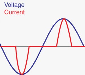
In short, a PFDistortion value close to 1.00 represents a system with very little harmonic distortion. The further the distortion PF value moves away from 1.00 the more harmonic distortion is present. However, a PF measurement by itself is somewhat lacking in that it gives no information to the magnitude of contributing harmonic distortion relative to the size of the utility supply.
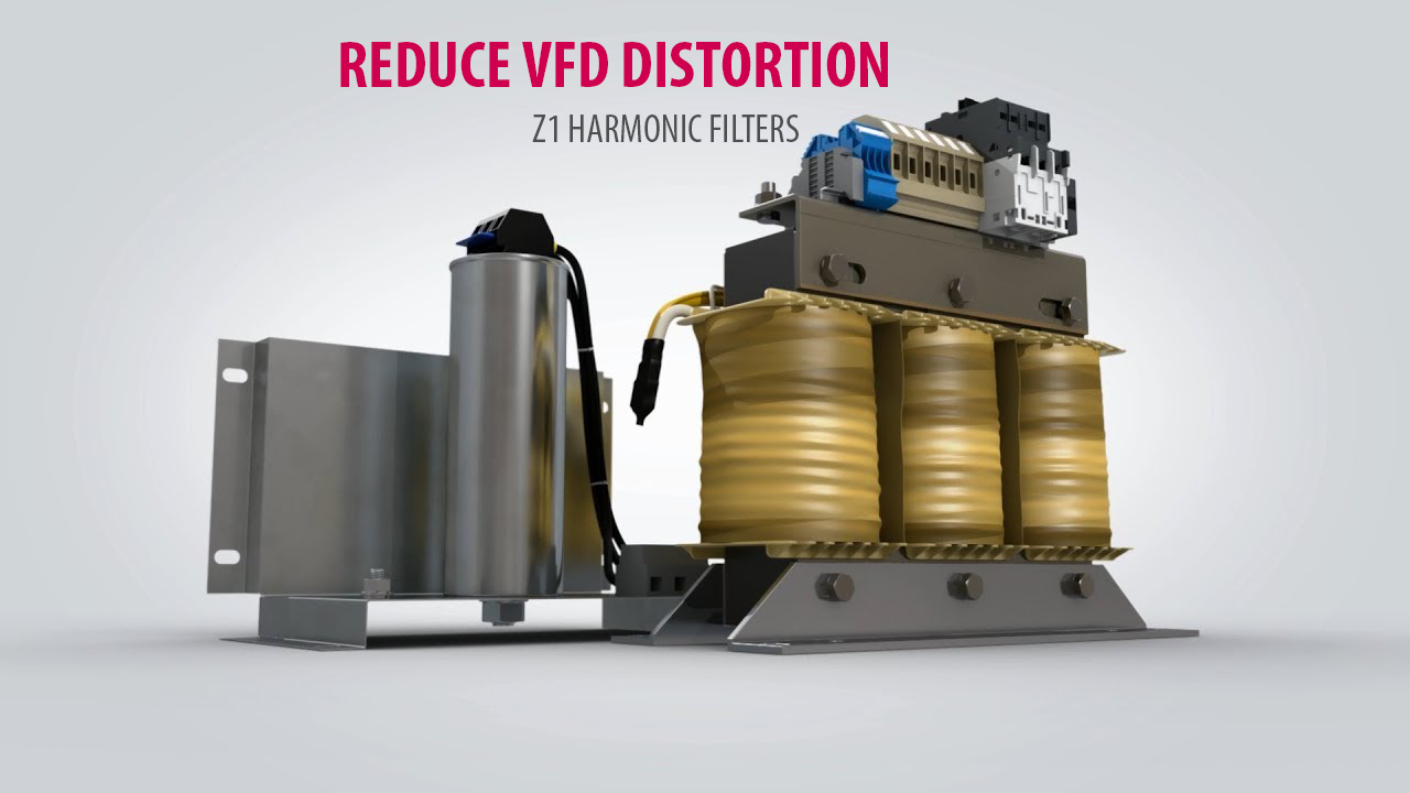
Do you want to discuss the benefits of using KEB harmonic filters with your elevators? Contact an application engineer today!
Related Articles


Let's Work Together
Connect with us today to learn more about our industrial automation solutions—and how to commission them for your application.