
Starting a Motor in 10 Steps
This is how to quickly and effectively start-up a servo motor using our S6-K drive. Utilizing the programming Wizards in KEB’s COMBIVIS 6 software, we can break down the process into 10 simple steps.
In this blog post specifically, we will be highlighting the startup of a KEB Dynamic Line III servo motor utilizing closed-loop control with encoder feedback. The general process will be similar for other motor types.
What do I need to get started?
Closed-loop control with encoder feedback is a VFD control method that utilizes measured speed feedback through an encoder device.
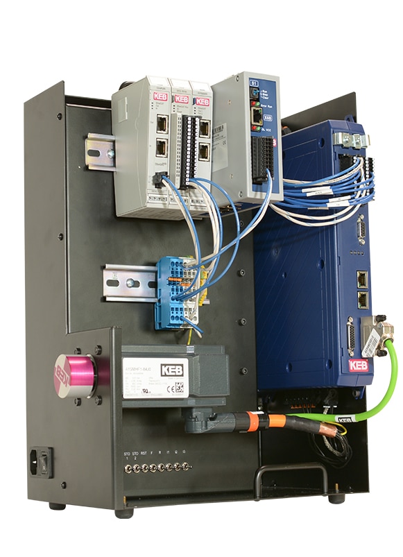
In general, there are (5) main components that will be required to startup your particular motor.
- Power Source (S6 has options for 1-phase and 3-phase input)
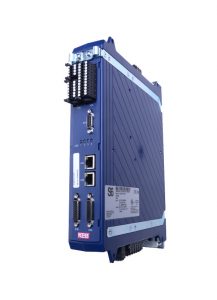
- S6 Servo Drive
- 3-phase AC motor (S6 runs either induction or servo motors)
- Encoder feedback device and encoder cable
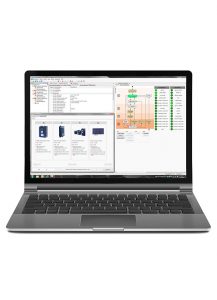
- Combivis programming software to configure VFD
Once we connect our power and devices in their respective manner, we can startup COMBIVIS 6 and soon begin programming.
Getting Connected to COMBIVIS 6
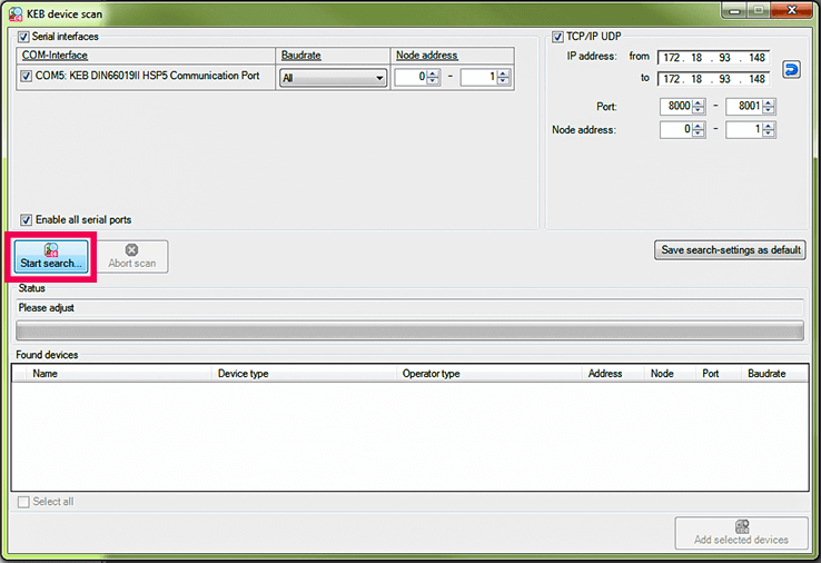
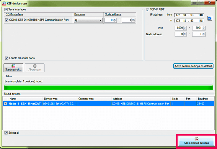
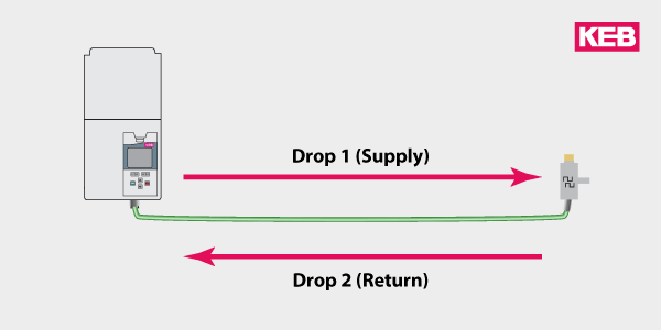
Before we can start programming, we first need to connect our drive to COMBIVIS 6 using the KEB USB-to-serial converter. We can then perform a device scan and add the S6-K drive to the COMBIVIS 6 project.
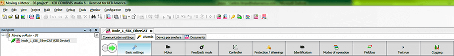
Once the S6-K has been connected to the project, we can open the interactive programming Wizards that are specially designed into the COMBIVIS 6 software for use with generation 6 VFDs (S6, F6, H6).
Now we can take a look at the start-up Wizards Tabs to get your motor spinning.
Now that all of our components are wired-up and connected, we can now dive into our 10 start-up steps.
The 10 Steps to Starting a Motor
Step 1: Restore factory default device settings
Major Tab: Basic settings
Minor Tab: Basic settings
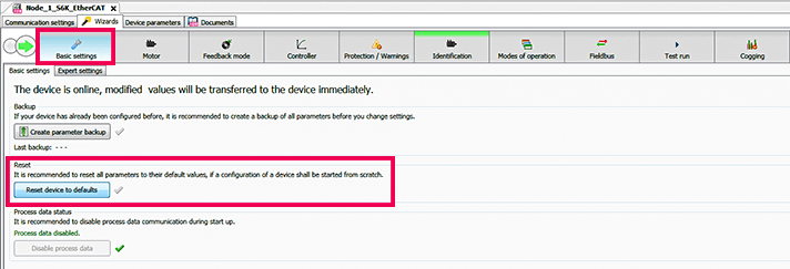
The first tab we will visit is the Basic settings tab. In this tab, the option we will want to choose is “Reset device to defaults”. This selection will clear any programming currently in the drive and restore the drive to its factory settings. New drives will ship from KEB with default settings but it is always a good idea to do this step in order to ensure you are starting with the defaults.
After the drive resets, we will move into the Motor Tab.
Step 2: Input motor nameplate data
Major Tab: Motor
Minor Tab: Motor data
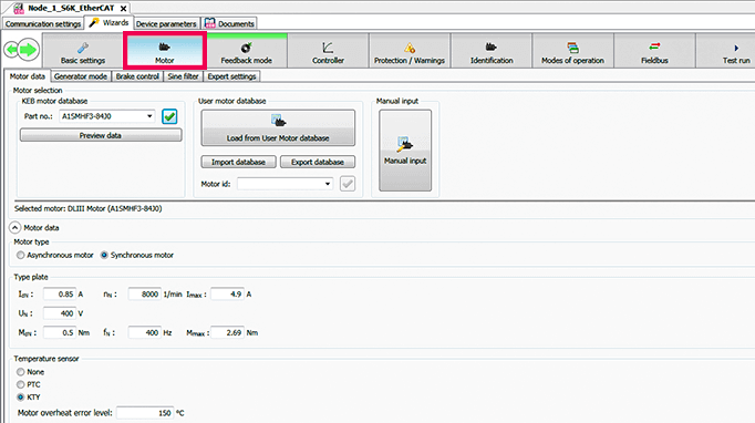
Inside the Motor tab, this is where we will input our motor-rated nameplate data. In the case of a KEB motor, we can utilize the KEB motor database to easily load the rated nameplate data. We will input our KEB motor part number into the database, which will automatically load the motor data. We can then confirm the motor type and the type plate data below. If you are using a non-KEB motor, simply select the “Manual input” button on the right, and input the rated data of your specific motor in the spaces below.
Next, if your motor has a brake, we will briefly jump into the Brake control tab.
Step 3: Activate brake control
Major Tab: Motor
Minor Tab: Brake control
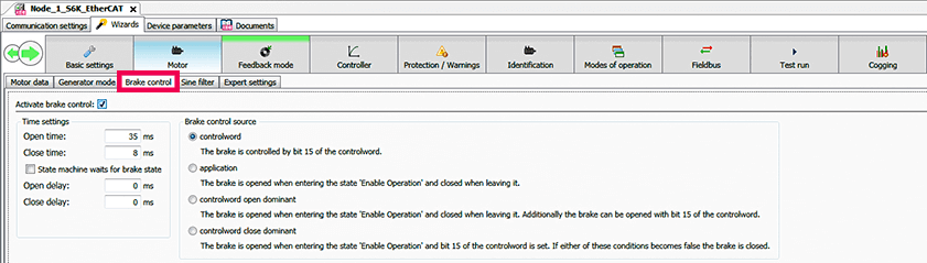
In the Brake control tab, we want to ensure that “Activate brake control” is selected so that we may operate the motor brake using the VFD/drive. In this tab, we can also set our brake release/open and engage/close times, if applicable. We will keep the brake control source as “controlword” so we can control the brake for the motor identification and test run.
Now we will enter into the Feedback mode tab.
Step 4: Select closed-loop control mode and speed control source
Major Tab: Feedback mode
Minor Tab: Wizard
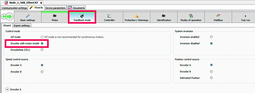
In the Feedback mode tab, we will set the control mode to “Encoder with motor model”; this is the control mode for closed-loop with encoder feedback. You may also see V/f mode and Encoderless (SCL) options. These are other available control modes that may require additional or different programming than what we are working with here.
We will set both speed control source and position control source to “Encoder A”.
Step 5: Set applicable encoder type
Major Tab: Feedback mode
Minor Tab: Wizard
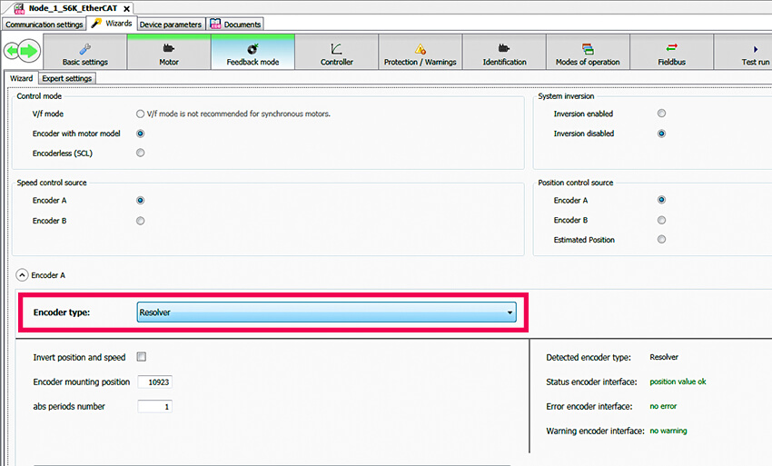
Expanding the “Encoder A” drop-down menu will expose an encoder type selection. Since we input the KEB servo motor part number in the Motor tab, the Resolver encoder type is already populated. This section is where you would select your encoder type and enter the Encoder mounting position, if known. If the mounting position is unknown, this can be calculated during the motor identification.
Next, we will quickly move to the Controller tab.
Step 6: Set motor inertia and load inertia, if known
Major Tab: Controller tab
Minor Tab: Speed controller
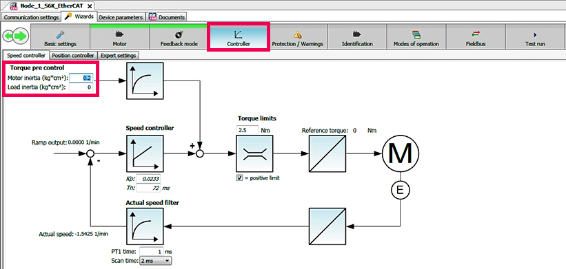
Set motor inertia and load inertia, if known
For the Controller tab, the only parameter to adjust at this time would be the motor and load inertia, if known. The motor inertia would be a parameter obtainable from your motor manufacturer, and in the case of our KEB motor, it is auto-populated from the KEB part number.
We are now ready to enter the Identification tab.
Step 7: Perform motor identification and detection of encoder mounting position
Major Tab: Identification tab
Minor Tab: Wizard
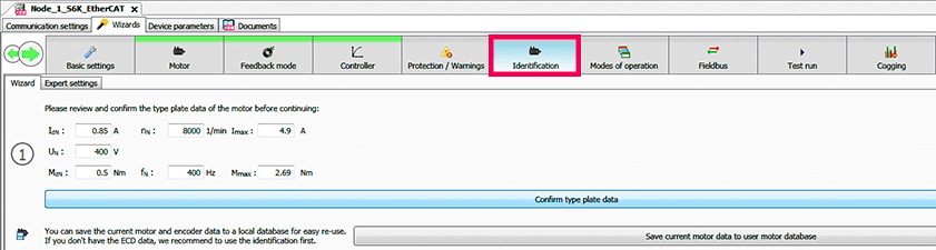
We start in the Identification tab by confirming our rated nameplate data. Once confirmed, a second box appears and offers added detection options for the identification.
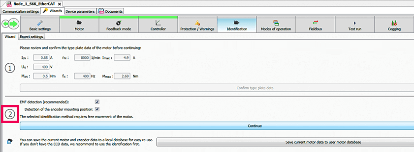
This is where we can select to detect the encoder mounting position. In the third box, there are (4) requirements that must be fulfilled to allow for motor rotation and identification; STO digital inputs, voltage supply, no error state, and brake released.
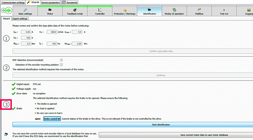
Once these (4) requirements are met, we can begin our identification, which will cause the motor to rotate. The identification must be performed under no-load conditions.
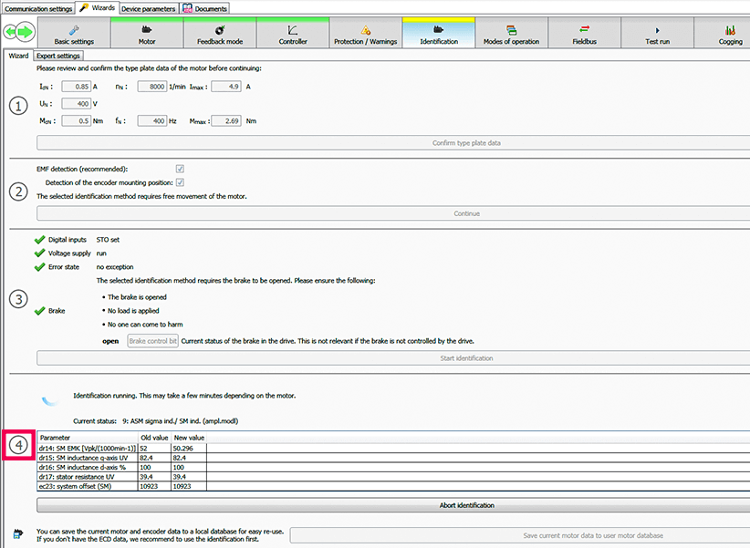
During and after the motor identification, a small table will populate with a few motor parameters and the encoder mounting position, and their respective “old” and “new” values. The “old” and “new” values represent the parameter value before and after the identification. Some parameters might be different after the identification, but this is expected as the identification now incorporates cabling and other realistic setup characteristics.
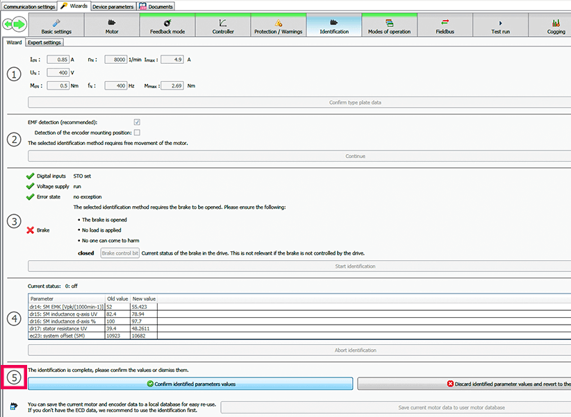
We can confirm the identified parameters and then move into the Modes of operation tab.
Step 8: Select “Velocity Mode”
Major Tab: Modes of operation
Minor Tab: Wizard
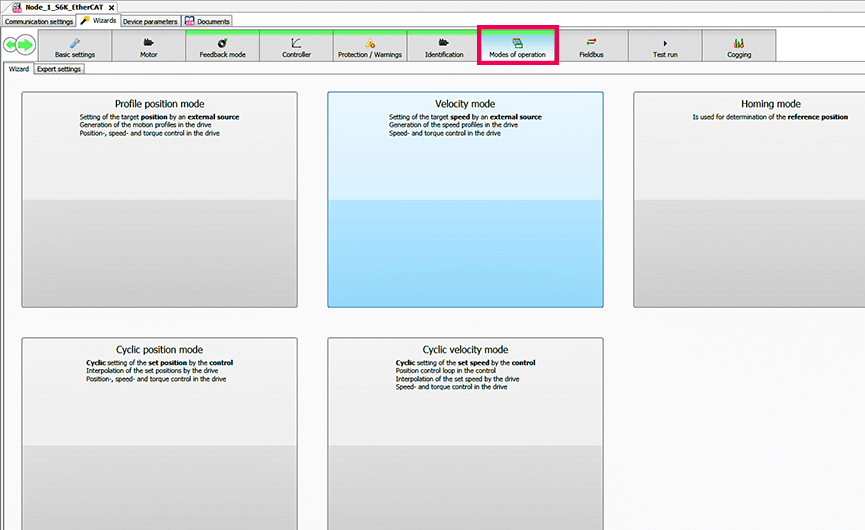
You will see (5) available modes of operation for this S6 drive. For our testing, we will choose “Velocity mode.”
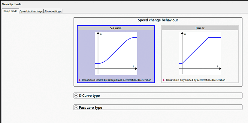
Step 9: Choose ramp mode and speed limit settings
Major Tab: Velocity mode pop-up
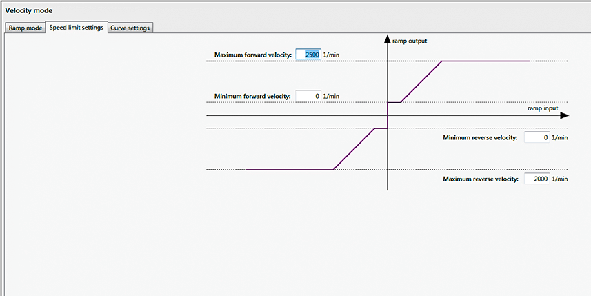
Minor Tab: Ramp mode and Speed limit settings
Once you select “Velocity mode”, a Velocity mode pop-up will appear. The ramp mode tab is where you can select between S-curve and linear ramp profiles. In the Speed limit settings tab, you can set your maximum and minimum velocities in each rotation direction.
When you select your speeds, click the “X” at the top of the Velocity mode pop-up.
We are now ready to test run the motor.
Step 10: Perform Test Run
Major Tab: Test run
Minor Tab: Start ‘test run’ wizard
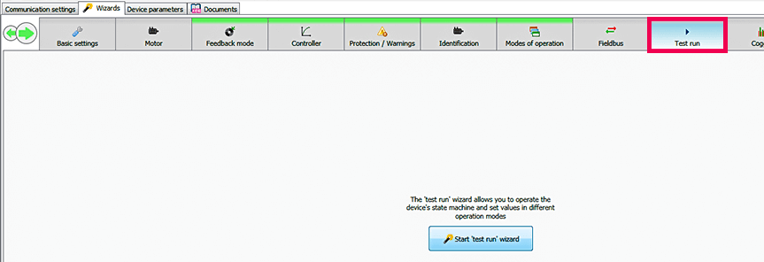
Click on the Test run tab and an available “Start ‘test run’ wizard” option will appear. Clicking on the “Start ‘test run’ wizard” will pull up the test run wizard window.
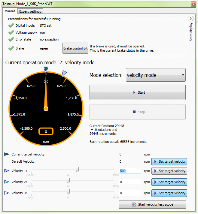
At the top of the test run wizard are the (4) preconditions for successful running, which were the same prerequisites for the motor identification. Once the (4) conditions are met, we can set a target velocity using the “Velocity 1” input near the bottom. The slider bar represents the maximum forward and reverse speeds you created in the Velocity mode tab.
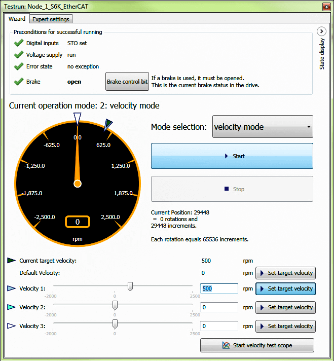
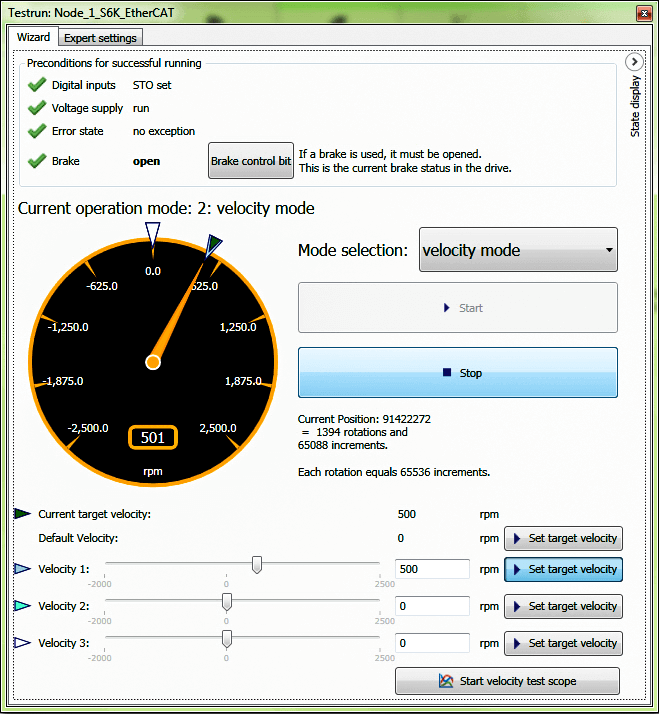
Once a speed is in the “Velocity 1” text box, it can be loaded into the drive using the “Set target velocity” button. Click “Start” when you are ready to spin the motor. The motor will spin and the encoder speed will be tracked on the speedometer.
Conclusion
You have now quickly and effectively started a motor with an S6 Servo Drive.
You may have noticed that we skipped over some tabs in the COMBIVIS 6 Wizards, such as Protection / Warnings, Fieldbus, and other Controller tab parameters. These are important tabs that you would visit to complete the commissioning of your drive and motor for successful integration into your industrial machine.
If you are interested in visiting with KEB sales or engineering regarding your new application, please contact us using the form below.
Related Articles
Let's Work Together
Connect with us today to learn more about our industrial automation solutions—and how to commission them for your application.