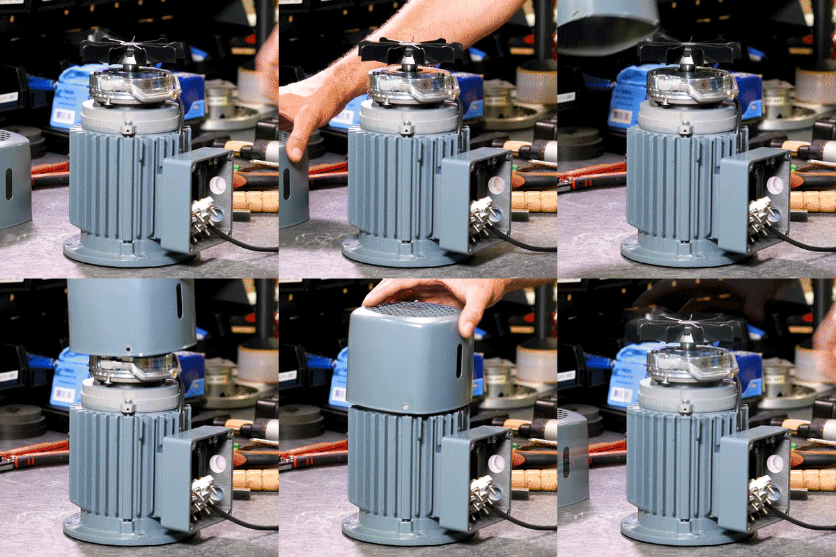
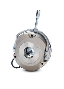
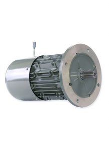
Electric motor brakes are critical safety components that decelerate or securely hold motor loads when power is intentionally cut or accidentally lost.
These electromagnetic braking systems form the backbone of industrial automation safety, preventing catastrophic failures and ensuring precision control across manufacturing, material handling, and process automation applications.
This comprehensive guide explains how electromagnetic brakes work, their types, applications, and sizing tips for safe, efficient industrial automation performance.
KEB has become a top manufacturer of high-performance motor brake solutions because of its 50+ years of specialized expertise in demanding industrial markets.

Why Electric Motor Brakes Matter in Industrial Applications
In industrial applications, unexpected power loss can create dangerous situations with rotating machinery, falling loads, or runaway equipment. Motor brakes provide essential safety by:
• Preventing accidents when power fails unexpectedly
• Enabling precise positioning for automated systems
• Protecting equipment from damage during emergency stops
• Meeting safety regulations for industrial machinery
The implementation of electric motor brakes provides safety benefits while simultaneously improving equipment operational performance. The system enables users to achieve better load management and shorter cycle times and enhanced positioning system accuracy.
How Electric Motor Brakes Work
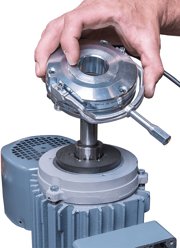
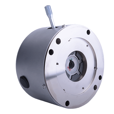
KEB spring-set brakes, referred to as Combistop brakes, are considered fail-safe due to their engagement method. While other designs use rare earth magnets or a simple electromagnetic coil, the Combistop uses springs to generate the braking force. This means that if the brake should ever fail to receive power, the springs will maintain engagement.
Electromagnetic Braking Process
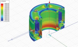
The brake coil receives DC voltage when the motor receives power which generates a magnetic field that moves the armature plate away from the friction disc to enable shaft rotation.
When power is cut, the magnetic field collapses, and preloaded springs push the armature plate back against the friction disc to create holding torque.
The system design enables automatic stopping of motion when power supply fails which creates an extremely dependable safety mechanism. The response speed of the system depends on three main factors which include coil inductance, supply voltage, and power switching side (AC vs DC).
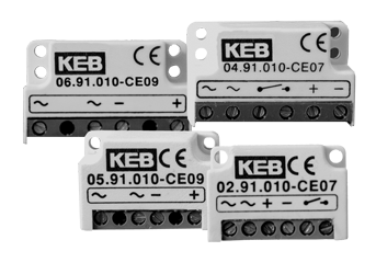
KEB’s bridge rectifier converts AC power into DC power at a half or full wave and produces consistent pull-in and drop-out performance for applications where only AC power is available.
Flexible Voltage Options
KEB electromagnetic brake coils can be wound for nearly any voltage requirement, providing maximum flexibility for international equipment manufacturers. Common configurations include:
• 12VDC and 24VDC for battery-powered or mobile machinery applications
• Standard industrial voltages (105VDC, 205VDC) for factory equipment
• Custom voltage specifications to match unique system requirements
For facilities using AC power, KEB offers integrated bridge rectifiers that easily convert AC to DC, ensuring consistent performance and quick brake release.
By matching the brake coil voltage to the available power source, engineers can optimize system performance. This reduces release time, improves energy efficiency and helps avoid burning out the coil.
Types of Motor Brakes
KEB designs and manufactures multiple brake types to meet diverse industrial requirements. Each operates on electromagnetic principles but is optimized for specific torque, space, and control needs.
Mechanical Spring-Set Brakes
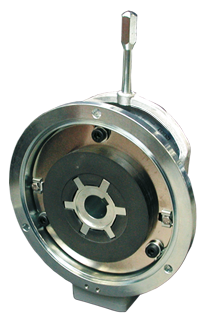
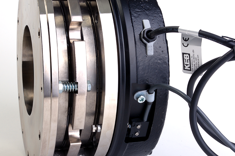
Mechanical spring-set brakes (also called spring-applied brakes) are the most widely used style for industrial motion control. These fail-safe brakes engage automatically when power is removed, ensuring dependable holding and stopping in the event of an emergency or power loss.
In normal operation, the brake releases when the coil is energized, pulling the armature plate towards the coil housing and increasing the air gap between the friction material and secondary mounting surface, allowing shaft rotation. When voltage is removed, the springs engage to clamp the friction surfaces and stop the motor shaft.
This design delivers reliable static and dynamic braking performance across a range of applications, from servo axes to hoists, conveyors, and stage automation.
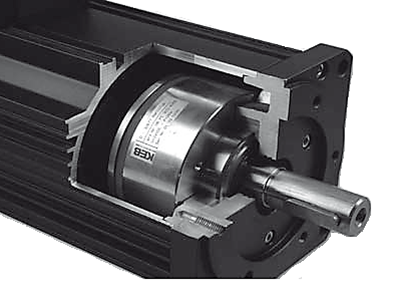
KEB’s mechanical spring-set brakes are available in multiple frame sizes and torque ratings, providing engineers with precise control over system response to dynamic and static loads. They are designed for easy integration with servo and induction motors, and optional microswitches can be installed for brake status feedback in advanced safety systems (application dependent).
KEB also offers alternative brake technologies designed for applications that demand unique operating principles or performance characteristics beyond standard spring-set designs.
Permanent Magnet Brakes
Permanent magnet brakes are ideal for high-precision positioning and power-off applications. Instead of relying on mechanical springs, these brakes rely on permanent magnets placed within the brake housing to generate a permanent magnetic field.
When DC voltage is applied, an electromagnetic field is generated in the opposite polarity and negates the one generated by the permanent magnets and releases the brake. This design requires no power consumption while holding and delivers extremely consistent torque with minimal air-gap wear.
As a result, permanent magnet electromagnetic brakes are well-suited for:
• Robotics and collaborative automation systems
• Energy-efficient industrial braking systems where long-term holding without power draw is critical
• Precision servo applications requiring minimal backlash
• Medical and laboratory equipment demanding silent operation
Because of their precise and energy-conscious operation, permanent magnet brakes are frequently specified for servo-driven applications where fine motion control and minimal backlash are required.
Due to current global policies, these brakes can only be used for commercial purposes and cannot be integrated into any military based projects.
Power-On Brakes
Power-on brakes (also known as electromagnetic motor brakes) operate in the opposite manner of spring-set designs. These brakes are engaged when power is applied and they release when voltage is removed.
They are often used in specialized applications that require the brake to engage only during machine operation. One example is when dynamic braking is needed to stop moving loads without continuous holding torque.
Power-on brakes are well-suited for:
• Reverse-operation drives and tensioning systems
• Test stands and dynamometer applications
• Automated processes that demand precise timing and engagement control
• Clutch-brake combinations for rapid cycling operations
• Revolving doors and turnstiles
KEB offers custom coil configurations and mounting designs for OEMs, allowing engineers to fine-tune response characteristics for complex motion profiles or unique system requirements.
Applications for Motor Brake Systems
KEB motor brakes are deployed across a wide range of industrial brake applications, supporting equipment that demands precision, safety, and reliability. Key application areas include:
Material Handling and Logistics
• Automated guided vehicles (AGVs) requiring fail-safe stopping
• Conveyors and sortation systems with precise positioning needs
• Palletizers and packaging equipment demanding rapid cycling
Lifting and positioning equipment:
• Hoists and cranes
• Stage machinery and entertainment rigging
• Winders and unwinders in converting and textile applications
Advanced automation systems:
• Collaborative robotics systems
• Servo-driven axes with high-precision positioning requirements
• Medical and laboratory automation demanding clean, quiet operation
Harsh Environment Solutions
KEB offers electromagnetic brake options that perform reliably in challenging industrial environments. The Type 28 spring-set brake, for instance, carries a NEMA 4X enclosure rating.
This makes it ideal for:
• Washdown areas in food and beverage processing
• Outdoor installations exposed to weather
• Marine and offshore applications
• Chemical processing facilities
Custom adaptations are also available for unique motion profiles, high-speed axes, and heavy-load systems. Whether a machine requires compact torque density, low-noise operation, or integration with servo feedback devices, KEB engineers can customize brake geometry, voltage, and friction linings to meet specific performance needs.
Double C-Face Brakes: Modular Flexibility
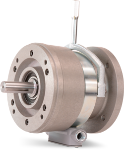
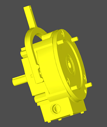
The KEB Type 17 Double C-Face Brake provides outstanding versatility for both new installations and retrofit applications. Its through-shaft architecture allows the motor and gearbox to remain perfectly aligned while the brake is replaced, minimizing downtime and preserving machine accuracy.
This modular, inline design simplifies maintenance and makes the brake ideal for systems where serviceability and precision alignment are critical.
Integrated Design
The Type 17 operates as a power-off DC spring-set brake, delivering fail-safe holding when power is removed. It incorporates integral NEMA input and output flanges for inline motor mounting and offers a through-shaft configuration that streamlines integration in compact or modular assemblies.
Installation Flexibility
Engineers can easily install the brake between a NEMA C-Face motor and gearbox, allowing the system to be serviced in sections rather than as a complete assembly. This design is compatible with 56C through 286TC NEMA motor frames, supporting a wide range of industrial configurations and torque capacities.
Standard Features
Each Type 17 electromagnetic brake is engineered with:
• Multiple magnet voltage options for global compatibility
• Integrated conduit box for straightforward wiring
• NEMA 4 environmental protection for reliable operation in harsh conditions
• Manual hand release for safe, controlled disengagement during maintenance
By combining modularity with robust construction, the Type 17 Double C-Face Brake exemplifies KEB’s approach to practical, service-friendly electromagnetic braking system engineering. This design enables users to improve uptime, simplify maintenance, and enhance machine flexibility.

How to Size and Select the Right Brake
Selecting the proper electric motor brake begins with understanding torque, inertia, and duty cycle. The goal is to achieve fast, safe stopping without overheating or over-sizing the brake.
Torque Calculation for Industrial Braking Systems
Brake torque must counteract the reflected inertia of the load. Start by calculating the total reflected inertia (J) at the brake shaft, including load, couplings, and gear reduction. With that value and the desired stop time (t) and operating rotational speed (ω), you can estimate torque using the simplified relationship:
T = J × (ω / t)
This provides a baseline for static holding or controlled deceleration for dynamic stops. In practice, engineers typically apply a safety factor of 25–50% to account for wear, friction variability, and temperature effects.
Thermal Management
Thermal limits are just as important as torque when sizing industrial braking systems. Each stop converts kinetic energy into heat, so it’s critical to verify:
• Thermal energy per stop: E = 0.5 × J × ω²
• Total number of stops per hour
• Ambient temperature conditions
• Available cooling methods
Electrical Characteristics and Response Time
Electrical characteristics also play a crucial role in motor brake selection. Air gap, voltage tolerance, and coil response influence release time and braking consistency. For AC-fed systems, a bridge rectifier is commonly used to supply DC power for stable coil operation and predictable release behavior in electric motor brake applications. However switching the brake on and off is usually recommended on the DC side of the bridge rectifier as to decrease the delay in engagement.
Application-Specific Sizing Considerations
Sizing electromagnetic brakes in real applications often involves balancing torque margin, thermal load, and physical space constraints:
• For vertical axes or high-torque loads: A spring-applied electromagnetic brake provides robust holding even during power loss
• In servo-driven or continuous-duty systems: A DC motor brake with dynamic capability may be preferred for controlled deceleration
• For high-cycle applications: Consider thermal capacity and wear characteristics carefully
KEB’s engineering team assists OEMs and machine builders by configuring electromagnetic brake performance for a range of duty cycles, stop frequencies, and temperature conditions. This data-driven approach ensures that every industrial motor brake meets both performance and safety requirements while optimizing cost and service life.

Maintenance and Safety Best Practices
Routine maintenance is essential to ensure reliable performance and long electromagnetic brake life. The correct inspection interval depends on factors such as operating frequency (duty cycle), ambient conditions, and load characteristics.
In high-duty-cycle applications or environments exposed to dust, oil, or humidity, more frequent inspections of industrial braking systems are recommended.
During scheduled maintenance of brakes, operators should:
• Measure the air gap between the armature plate and the friction disc
• Verify coil resistance to ensure proper electromagnetic function
• Inspect the friction lining for wear or contamination
• Check mounting bolts and alignment for security
• Test manual release mechanisms for proper operation
• Tighten hub set screws to maintain its alignment with the shaft
Common Contamination Issues
Contamination by oil, grease, or process residue is one of the most common causes of electromagnetic brake performance degradation and can lead to torque loss or inconsistent release behavior. Cleaning and verifying alignment during service prevents premature wear and maintains reliable stopping torque in electric motor brake systems.
Electrical System Verification
Electrical parameters also play a key role in electromagnetic brake longevity. Overvoltage or undervoltage conditions can affect coil performance and cause erratic pull-in or drop-out response times.
Ensuring that rectifiers, control circuits, and power supplies are functioning within specification reduces stress on the electromagnetic components and prevents thermal overload.
KEB recommends establishing a preventive maintenance schedule that includes functional testing and torque verification under static load. When properly maintained, KEB electromagnetic brakes provide consistent performance over millions of cycles in demanding industrial applications.
Motor Brake Safety Standards and Compliance
Motor brake safety extends beyond component reliability in industrial braking systems. It’s also a matter of regulatory compliance and system integration.
KEB’s brakes are manufactured to meet global quality and safety standards, including:
• UL and CSA for electrical safety in North American markets
• ISO 13849 for safety-related parts of control systems
• IEC 61508 for functional safety in machine control systems
• CE marking for European conformity
These standards define how electromagnetic brakes interact with emergency stop functions and safe-torque-off circuits, ensuring that the braking system can respond correctly during power interruptions or system faults.
Compliance with these guidelines supports machinery certification and gives OEMs confidence that the electromagnetic braking solution meets performance and safety integrity requirements for global markets.

KEB: Your Trusted North American Brake Partner
Electric motors power countless industrial applications, and most require reliable braking systems. KEB’s combination of experience, quality, and local capabilities makes us the ideal partner for your motor brake needs.
Local Capabilities
KEB operates a 150,000 sq. ft. ISO 9001:2015–certified design and production facility in the United States. This enables fast turnaround, responsive technical support, and short lead times for North American customers. With local manufacturing and engineering resources, KEB can design, build, and test solutions that meet demanding application requirements.
Quality Commitment
Every KEB brake is built using high-quality materials and precision manufacturing processes to ensure consistent performance and long-term reliability. Comprehensive testing and quality assurance procedures verify torque output, response time, and thermal performance – critical parameters for safety and uptime in industrial environments.
Engineering Support
KEB’s experienced engineers assist OEMs and machine builders in selecting or customizing the correct brake for each application. Whether a project requires a standard configuration or a specialized design, our team works closely with motor manufacturers to ensure proper mechanical and electrical integration. This collaborative approach results in optimal system performance and simplified assembly for end users.
Ready to explore how KEB motor brakes can enhance your application’s safety, precision, and performance? Contact our team to learn more about our industrial automation solutions and discuss your project requirements with a KEB application engineer.

FAQ
How do I calculate the required brake torque?
Brake torque is determined by the reflected inertia of the load and the desired deceleration time. The simplified formula T ≈ J × (ω / t) can be used, where J is the total inertia at the brake shaft, ω is the initial angular velocity, and t is the stop time. It’s recommended to include a 25–50% safety factor to account for variables such as friction variation, temperature, and wear.
Can a motor brake be used for dynamic stopping?
Yes – certain electromagnetic motor brake designs are suitable for dynamic stopping, not just static holding. However, when brakes absorb kinetic energy during repeated stops, the generated heat must be within the brake’s rated thermal capacity.
How often should motor brakes be serviced?
Service intervals depend on cycle rate, operating environment, and application criticality. As a general guideline, brakes should be inspected every 5,000 to 10,000 operating hours.
What causes brake failure?
The most common causes include contamination, overvoltage, mechanical misalignment, improper air gap distance and excessive heat buildup. Oil or grease on friction surfaces can reduce torque, while overvoltage or poor electrical connections can damage the coil or rectifier.
What safety standards apply to motor brakes?
KEB’s industrial motor brakes are designed and tested in accordance with international safety and quality standards, including UL, CSA, CE, ISO 13849, and IEC 61508.
Let's Work Together
Connect with us today to learn more about our industrial automation solutions and how to commission them for your application.
"*" indicates required fields