
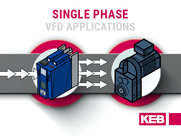
Single Phase VFD Applications – Sizing and Selection
There is often a desire to vary motor speeds. This is not possible when motors are connected directly to a fixed-frequency power source. The most common solution that allows variable speed control is to add a VFD to a motor. However, single-phase applications present a challenge since nearly all single-phase motors cannot be operated with a VFD.
The solution, as outlined here, is to use a three-phase motor with a VFD that allows for a single-phase input.
Sizing VFDs for Single Phase Applications
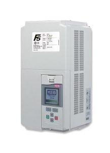
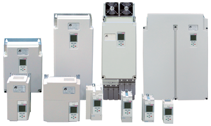
Small VFDs are often dimensioned and rated to handle the input power through a single phase. However, larger drives typically list their three-phase input ratings as standard. Single-phase input is likely possible but special precautions should be taken. This post describes the process for dimensioning a KEB F5 VFD for single-phase inputs.
Step 1 – Size input rectifiers
Since the current through a single input rectifier is going to be higher through one phase rather than through three phases (this is because a system supplied by a single-phase input needs the current of three-phase system times √3 to produce the same amount of power), it is necessary to upsize the input rectifier stage of the drive to match the higher current requirement. This can be done by selecting an inverter in the correct voltage class that has a rated output current of at least 2x the motor full load current.
Step 2 – Size DC bus capacitors
Rectifying power through a single phase produces more current ripple on the DC bus capacitors, so additional bus capacitance is needed to smooth the associated ripple. To ensure that the drive selected in step 1 has the necessary DC bus capacitance, find the drive that has a rated output current equal to or slightly greater than the full load current of the motor. Refer to the capacitance chart and see if the drive selected in step 1 has a DC bus capacitance that is approximate 2x the drive selected here. If this is the case, the drive selected in step 1 can be used for your single-phase application. If the capacitance is below the 2x requirement, find the next largest drive that has double the capacitance and use that one for your application.
| Voltage | Housing | Size | DC Bus (μF) |
|---|---|---|---|
| 230V | E | 13 | 3280 |
| E | 14 | 4100 | |
| G | 14 | 3280 | |
| G | 15 | 4000 | |
| H | 15 | 3600 | |
| H | 16 | 5400 | |
| H | 17 | 8800 | |
| H | 17 | 8800 | |
| R | 19 | 15600 | |
| R | 20 | 16500 | |
| R | 21 | 19800 | |
| 460V | E | 13 | 705 |
| E | 14 | 820 | |
| E | 15 | 1230 | |
| G | 15 | 880 | |
| G | 16 | 1230 | |
| G | 17 | 1500 | |
| H | 17 | 1800 | |
| H | 18 | 1800 |
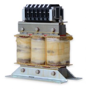
Step 3 – Install 5% reactor
Single-phase supplies have extremely high current spikes and will cause more mains distortion and DC bus capacitor heating (heat = shorter VFD lifetime). Install a 5% choke at the input of the inverter. Below is a chart that provides a drive size based on voltage class and motor full load current for single-phase applications. It should be possible to simply match your voltage class and FLA to the chart and select the correct drive for your application.
| Voltage class | Motor FLA | Correct drive size |
|---|---|---|
| 230V | 10-28A | 16F5A1H-Pxxx |
| 28-42A | 17F5A1H-Pxxx | |
| 42-57A | 19F5A1R-Pxxx | |
| 57-65A | 20F5A1R-Pxxx | |
| 65-77A | 21F5A1R-Pxxx | |
| 460V | 0-11A | 15F5A1E-Rxxx |
| 11-17A | 17F5A1G-Rxxx | |
| 17-20A | 18F5A1H-Rxxx | |
| 20-26A | 19F5A1H-Rxxx | |
| 26-33A | 20F5A1H-Rxxx | |
| 33-48A | 22F5A1R-Rxxx | |
| 48-68A | 23F5A1U-Rxxx | |
| 68-86A | 24F5A1U-Rxxx | |
| 86-115A | 26F5A1U-Rxxx |
Questions on Single Phase Options
Do you have questions on sizing a VFD for single-phase applications? Contact a KEB America Sales Engineer today.
Related Articles

Let's Work Together
Connect with us today to learn more about our industrial automation solutions—and how to commission them for your application.