
Selecting Spring-set Brakes in Dynamic Braking applications
Industrial machines like AGVs or autonomous robots will often use regenerative motor braking to slow and stop the vehicle in a controlled and safe manner. However, sometimes a dynamic spring applied electric braking system is preferred as they offer fail-safe performance guaranteeing the vehicle will stop in the event of power loss.
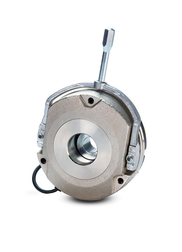
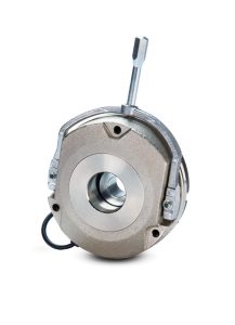
KEB’s spring-applied “Type N” brakes offer a simple dynamic braking solution for a wide range of vehicle sizes and speeds. Spring-set brakes utilize a thick friction lining that can withstand the energy dissipated during dynamic braking operation and allow for wear over time similar to brake pads on a car.
This article will walk through the selection process to properly size a power-off brake according to specific vehicle constraints. The first step will be to identify the vehicle constraints that will be needed to properly size the braking requirements, once these are identified you can use the KEB spring-applied data to properly size.
Note: this guide is purely theoretical and is solely intended to give a general understanding of how to approach brake sizing. Variables such as temperature, humidity, brake slippage, brake air-gap, brake part wear (armature, secondary friction surface), etc. are either assumed perfect or neglected. As all of these variables will be application specific the only true way to determine brake feasibility is to test in the actual application and environment in which the brake will be used. This is the responsibility of the customer.
Vehicle constraints
System Energy: Although system energy is comprised of many additive components (vehicle inertia, wheel inertia, motor inertia, gearbox inertia, brake inertia etc.) a simple estimation can be made using the vehicle mass and speed. The kinetic equation for system energy (shown below) is typically acceptable for simple analysis.

Brake Speeds: nominal operating speed and e-stops: It is essential to determine the actual speed the brake will experience when operating normally and during an e-stop. Both speeds should be less than the listed “maximum operating speeds” of the selected brake. Typically, the brake is installed in line with the motor so the motor and brake speeds (rpm) are the same.
Brake Selection and Verification
Brake torque
Calculating the required brake torque is the first step in brake selection for dynamic applications. Sizing can be done based on inputs including motor speed and power, required stopping distance, required stop time, etc. Customers are responsible for sizing depending on the specific application requirements. Note that the KEB catalog ratings are the max-rated brake torque after a run-in process, it is up to the customer to size properly according to their required safety factor.
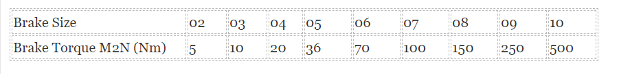
The KEB catalog-listed brake torque ratings are labeled “M2N.” As a rule of thumb, an engineer should double the required torque (i.e., if your system requires a 5 Nm brake, you should select a 10 Nm brake). However, know that brake torque will also affect stopping time, which also needs to be considered. If brake torque is heavily oversized, the brake can violently jerk the load to a stop; if the brake is undersized, it can lead to a slow and gradual stop. Therefore, it is important for the customer to consider the critical requirements of their application and to use these as the guiding factors for sizing.
See chart A: Type N Brake torque ratings for the respective brake size torque ratings.
Brake energy
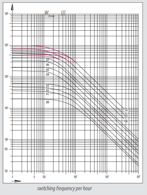
KEB spring-applied brakes can withstand a max amount of energy per stop in relation to the switching frequency. As you begin to stop more frequently the amount of energy the brake can withstand per stop decreases. This is because the brake needs time to dissipate the energy it absorbs during a dynamic stop. The remaining energy is added to subsequent stops if the energy is not dissipated fully.
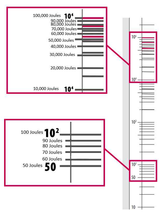
As seen below on Chart B: Friction Switching Frequency, switching at one cycle per hour yields the highest energy per stop ratings. As the cycles per hour increase, the energy the brake can withstand per stop decreases exponentially. The X-axis is your switching cycles per hour (log scale) and the y-axis is the allowable energy per stop at that cycle rate (log scale in Joules).
Quick guide to reading log chart axis: Whereas a standard line graph follows the relationship, where k is the multiplying linear factor that relates Y to X, in a logarithmic graph the relationship is. So the relationship is exponential vs. linear. See Chart C: Logarithmic Chart Intervals.
Note: this chart assumes the following speeds.
Size 00-07: 3000 rpm
Size 08-10: 1500 rpm
NOTE: energy dissipation is dispersed evenly among all brakes in the system. If the vehicle has two or more similar-sized brakes per system, the overall energy in the system can be divided by the total amount of brakes.
Once you have determined the allowable energy per stop with your given switching cycle frequency, compared it with the amount of energy in your system. If your system energy surpasses the max energy per stop per brake, the brake selected will not be acceptable for your application. If the energy dissipated in a single stop surpasses the allowable limit, the lining may glaze over resulting in reduced torque, or worst case permanent failure of the friction lining may occur.
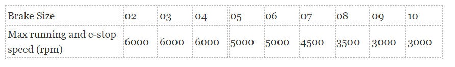
Brake speed: It is also important to ensure that the application running and e-stop speed is within the limits that the brake can withstand.
As with any rotating part, there will be an amount of runout. As the friction lining spins, excessive speeds will cause it to wobble and run on the friction surfaces. This will lead to premature and irregular wear and cause a premature brake system failure.
The friction lining is also limited by the speed at which it can withstand an emergency stop. If e-stopping occurs beyond this speed the friction lining can glaze over resulting in reduced torque or permanent failure.
See chart D: Max running and e-stop speed for the respective KEB Spring Applied brake size ratings.
KEB Spring Applied brakes for Dynamic applications
In summary, KEB’s spring applied brakes are well suited for dynamic applications but the system in question must be analyzed to ensure that the selected brake can withstand the requirements. The main limiting factors will be the amount of energy dissipated per stop at the required cycle rate and the running and e-stop speed.
Contact a KEB America engineer today to discuss KEB brakes for your application.
Related Articles
Let's Work Together
Connect with us today to learn more about our industrial automation solutions—and how to commission them for your application.