
Setup Guide: G6 IO-Link Communication with an ifm IO-Link Master
This post will overview the basics of the IO-Link protocol and the setup procedure to configure IO-Link communication between a G6 VFD and an ifm IO-Link master.
What is IO-Link?
IO-Link is a point-to-point communication protocol that allows for bidirectional data exchange between IO-Link devices. IO-Link specifications are defined in the international standard IEC 61131-9. IO-Link is commonly used to monitor, configure, and control devices using a PLC or other control device. Devices such as intelligent sensors, VFDs, relays, and other devices within the automation network are commonly used with IO-Link.
The benefits of IO-link become clear when considering the diagnostic information from a traditional sensor. An ON/OFF state or analog signal typically isn’t enough to determine a root cause of a problem. Reading status information and configuring parameters using IO-Link can greatly reduce installation and downtime. Machine efficiency can also be enhanced by monitoring and collecting data during machine operation.
Finally, IO-Link devices utilize a standard 3-wire or 5-wire cable with standard connectors for reduced wiring and simple configuration. IO-Link VFDs provide a relatively low-cost fieldbus drive and are ideally suited for the pump, fan, and conveyor applications.
IO-Link Basics
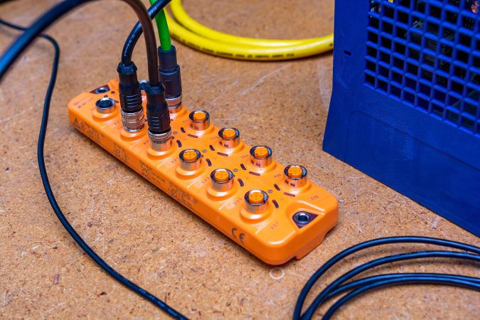
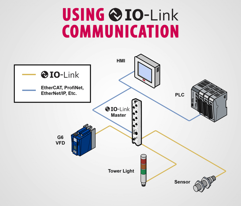
An IO-Link system includes an IO-Link master, IO-Link devices (sensor, VFD, etc.), connecting cables, and software for configuring IO-Link parameters. The IO-Link master is the gateway between the IO-Link devices and the control devices within the automation network using dedicated fieldbus ports and IO-Link ports. The IO-Link master transmits data from the connected IO-Link devices to the control devices over the fieldbuses supported by the master vendor.
Connection Interfaces
The point-to-point connection between the IO-Link master and IO-Link device uses a 3-wire or 5-wire unshielded cable with a four or five-pin connector. Standard M12 plug connectors are commonly used which allow for easy installation and operation in rugged environments. The pin assignment specified according to IEC 60974-5 includes 24V, 0V, and switching/communication signals. Depending on the vendor, the remaining available pins can be used for digital signals or additional power supply.
Protocol
Operating Modes: An IO-Link master can operate in various modes depending on application requirements. The operating modes are as follows:
- “IO-Link” (IO-Link communication)
- “DI” (digital input)
- “DQ” (digital output)
- “Deactivated” (unused ports).
Baud Rates: Depending on the IO-Link device 4800 baud, 38400 baud, and 230400 baud are all supported baud rates.
Data Types: Cyclic or acyclic data can be transmitted using IO-Link. Cyclic data is the “high speed” transmission channel, whereas acyclic data is the “low speed” transmission channel. Cyclic data is constantly transmitted and acyclic data is transmitted on request. The following data types are supported:
- Process Data: Cyclic data such as motor speed, or VFD status.
- Device Data: Acyclic data such as parameter values, or device identification parameters.
- Event Data: Acyclic data transmitted to notify the master of errors, warnings, or other important status information.
Device Profiles
Device profiles are used to standardize functionality, parameters, and data structure across different devices. Device profiles allow for easier programming without the need for expert knowledge of the device being used. Device profiles such as the “Smart Sensor Profile” and “Common Profile” are examples of device profiles used to decrease integration time.
Device Descriptions – IODD
An IODD (IO Device Description) contains information about each IO-Link device and is used to integrate each device into the IO-link system. The IODD includes communication information, parameter information, and other identification information. The IO-Link master will read the IODD file of each IO-Link device and assign parameters to its corresponding port.
G6 IO-Link Communication
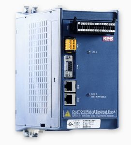
The KEB G6 VFD with IO-Link communication interface supports the “IO-Link” operational mode including cyclic and acyclic parameter transmission in accordance with IO-Link v1.0.
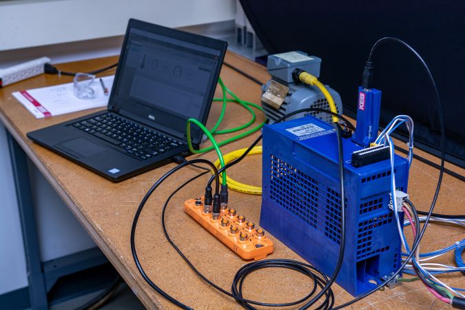
The setup procedure below overviews the IO-Link communication setup between an ifm IO-Link master (AL1342) and a G6 IO-Link drive. See the G6 IO-Link manual for wiring and pin assignment.
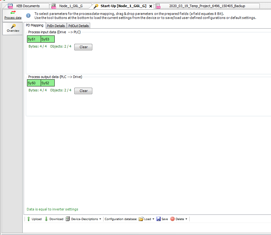
Step 1: Configure G6 Process Data
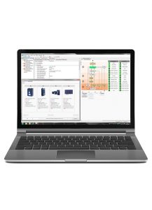
Process data parameters are configured using the setup wizard in Combivis 6. 4 Bytes of process data are available for input (e.g. set speed) and output data (e.g. drive status). Parameters can be dragged onto the process data slots (see picture below) on the wizard and the address of each parameter will automatically be written to the drive parameters (fb10-fb19).
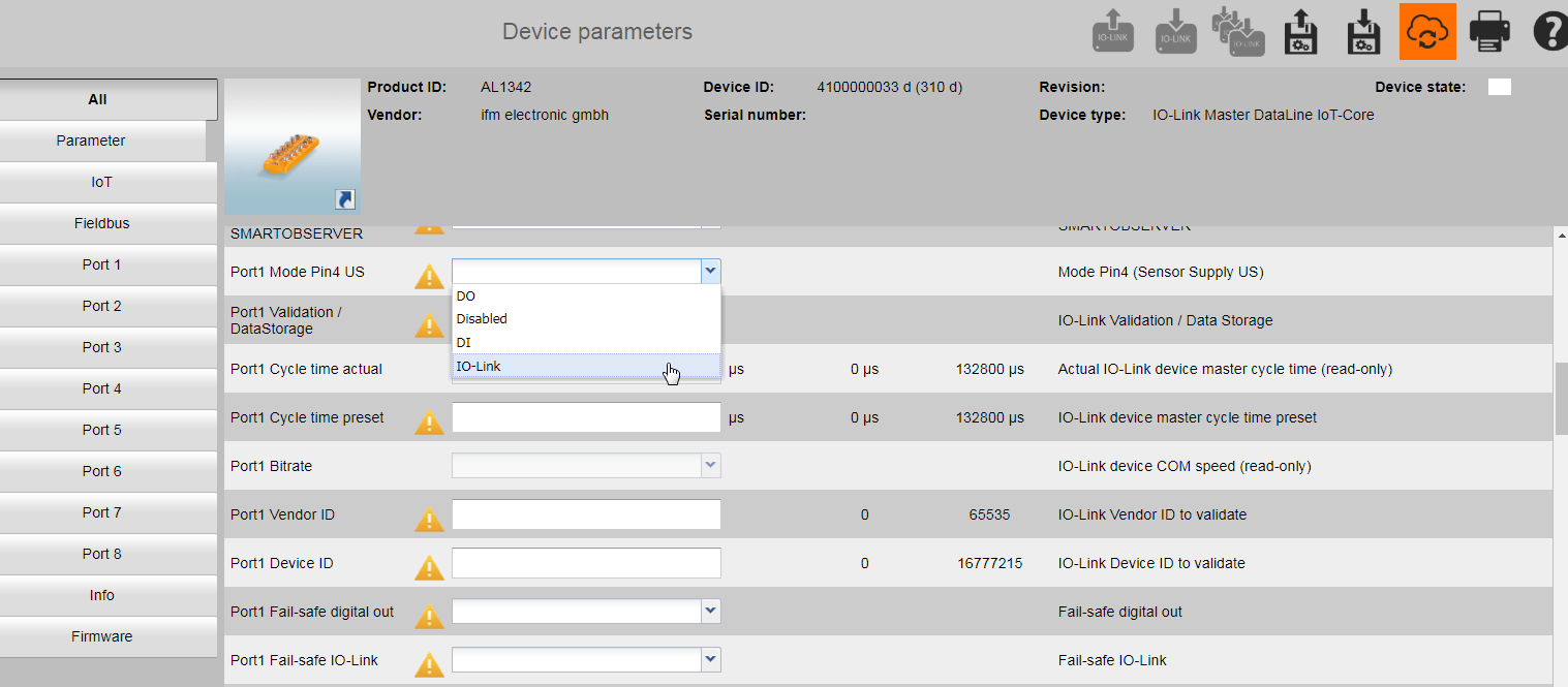
Step 2: Scan for ifm IO-Link Master and Configure IO-Link Port
Scan and connect to the ifm IO-Link master and configure the desired port to “IO-Link” (see picture below).
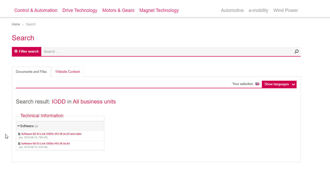
Step 3: Import G6 IODD into LR Device Software
The G6 IODD file can be downloaded from the KEB homepage under the search term IODD.
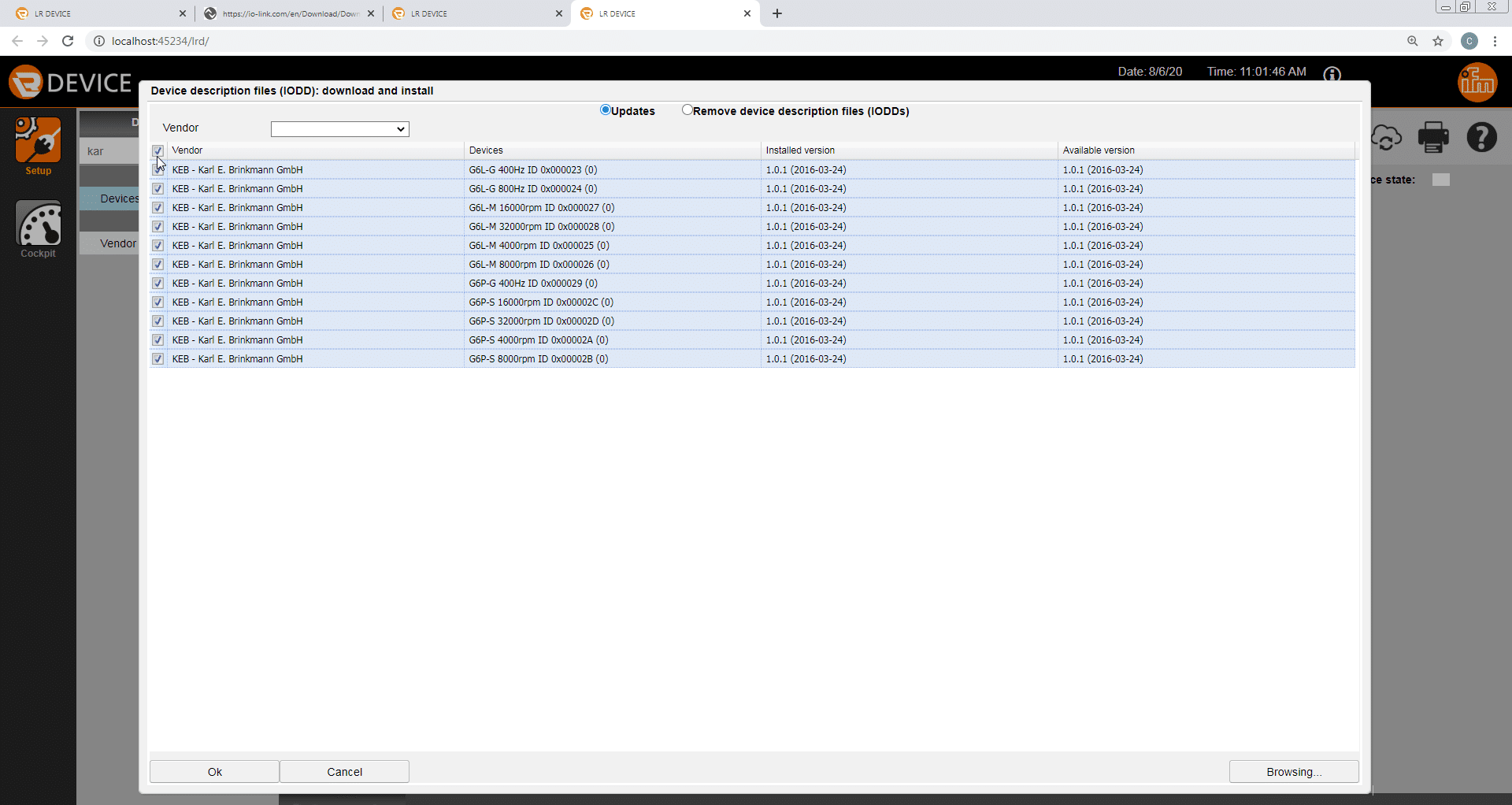
Next, select the “Search for updates of IODD files” icon and browse for the downloaded KEB IODDs.
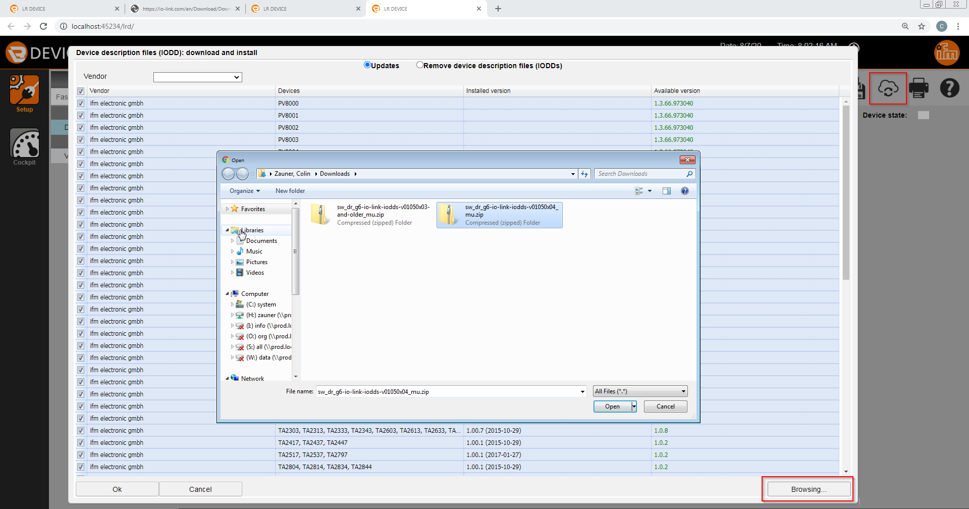
After selecting and opening the IODDs choose the desired G6 device and select open.
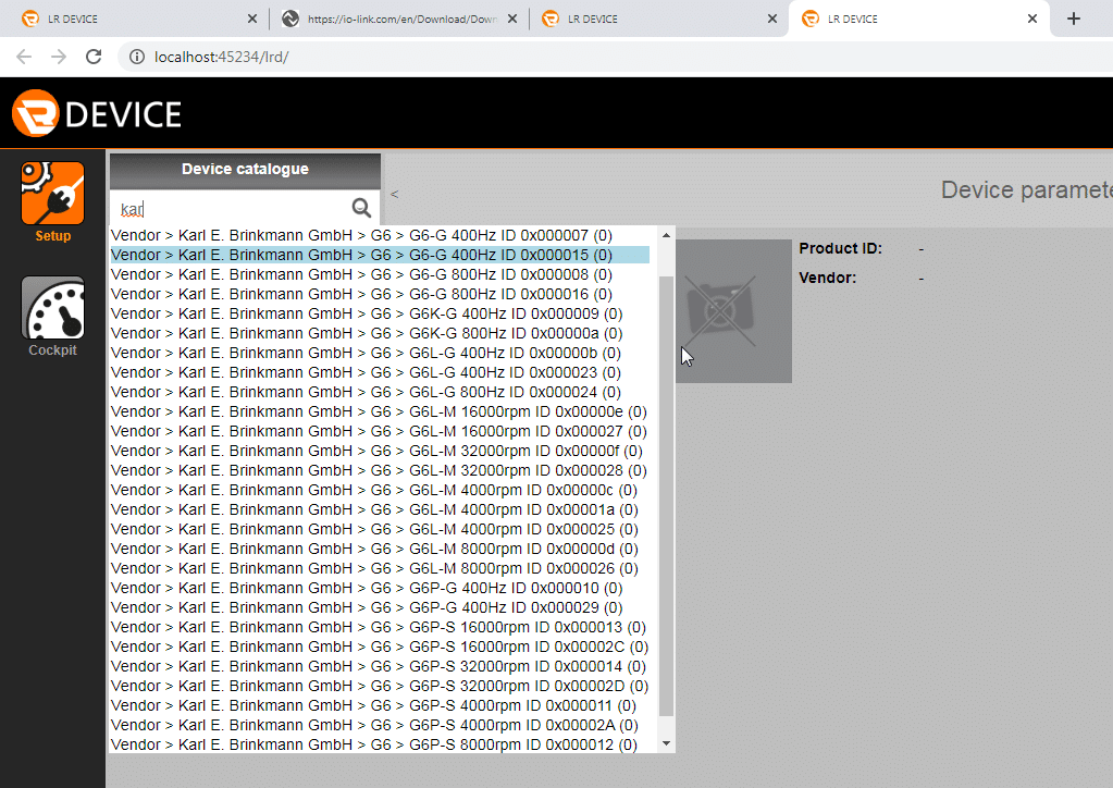
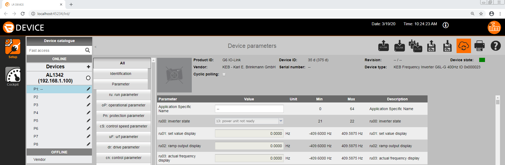
After importing the IODD files the device catalogue can be searched for any KEB G6 device and parameters can be viewed offline.
Step 4: Connect to G6 and Upload Project to the ifm IO-Link master
After successfully importing the IODD, scan for the G6. Finally, upload the project to the ifm IO-Link master by selecting the “write IO-Link parameters” icon.
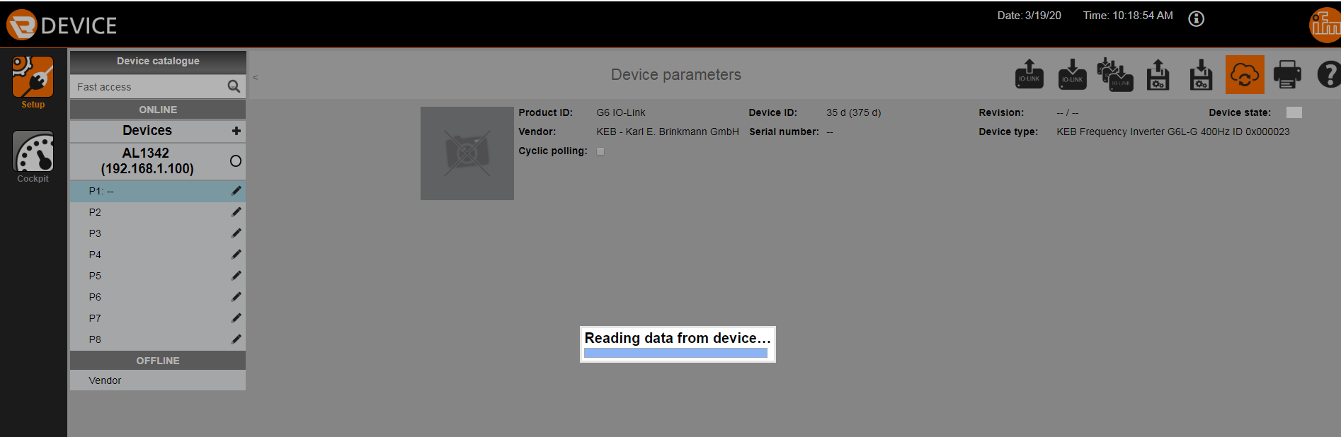
Once the IODD is imported into the LR device software and uploaded to the IFM IO-Link master the G6 parameters can be viewed and set directly from the LR device software (see picture below). It is now possible to communicate with the G6 VFD.
Step 5: Read/Write Data
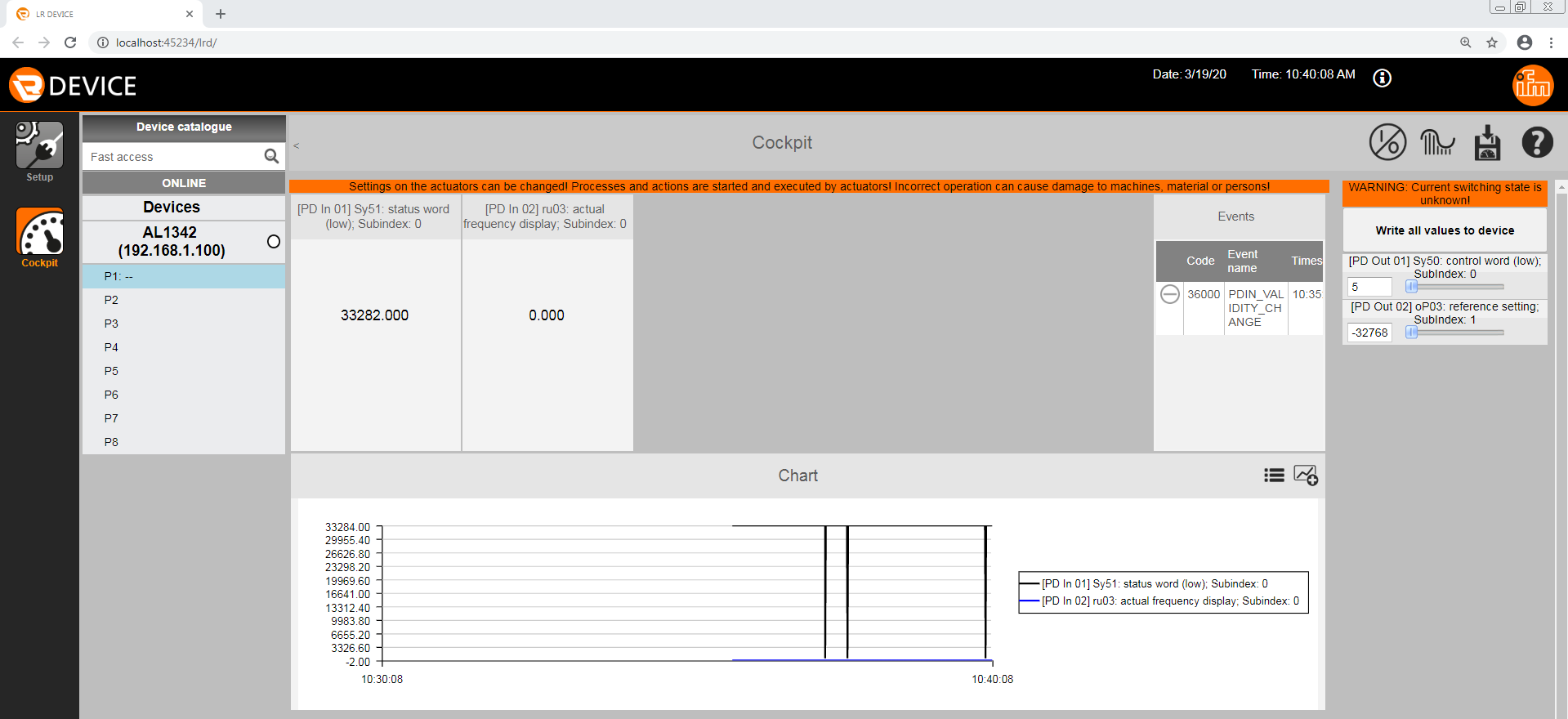
Process data can be read and written using the LR Device software Cockpit.
Spinning a motor using a KEB IO-Link drive is as easy as that. Discuss your application with a KEB engineer – contact us today!
Related Articles

Let's Work Together
Connect with us today to learn more about our industrial automation solutions—and how to commission them for your application.