
Short Circuit Current Rating (SCCR) and Fuse Selection
Protecting VFDs from short circuit current is essential when designing an electrical panel. But what exactly is the short circuit current rating (SCCR) of electrical components? More specifically, how is the SCCR calculated?
This post will go through a detailed procedure for determining the SCCR of a system, focusing on the differences between direct and isolation transformer fed systems.
What is the SCCR of a device and/or system?
The short-circuit current rating is the maximum amount of RMS (Root-Mean-Squared) current an electrical component can handle when using an overcurrent protection device, such as a fuse, or for a given amount of time at a specified voltage. The SCCR rating applies both for individual electrical components and for entire electrical assemblies or systems.
Figure 1 below shows an AC current waveform after a fault current situation occurs.
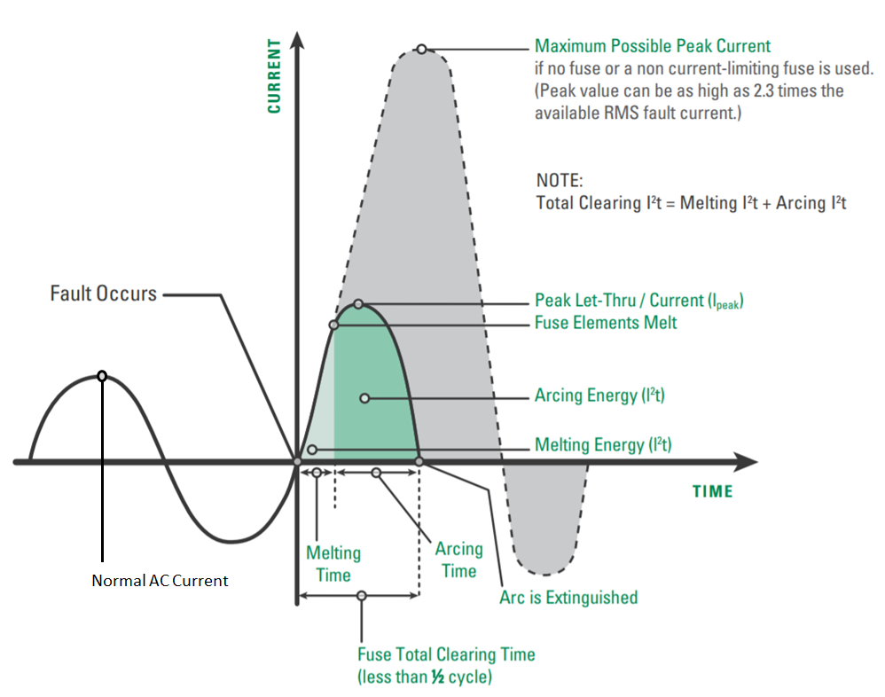
When selecting the proper fuse, it is important to look at the peak let-through current, Ipeak (Ampere) and nominal melting, I2t (Ampere Squared Seconds), ratings.
The Ipeak value is the peak amount of current a fuse will let through before clearing. The I2t value is the amount of thermal energy required to melt the fuse element.
Figure 2 below shows the Underwriters Laboratories (UL) published maximum allowable Ipeak and I2t values for fuses at 100kA and 200kA fault current levels.
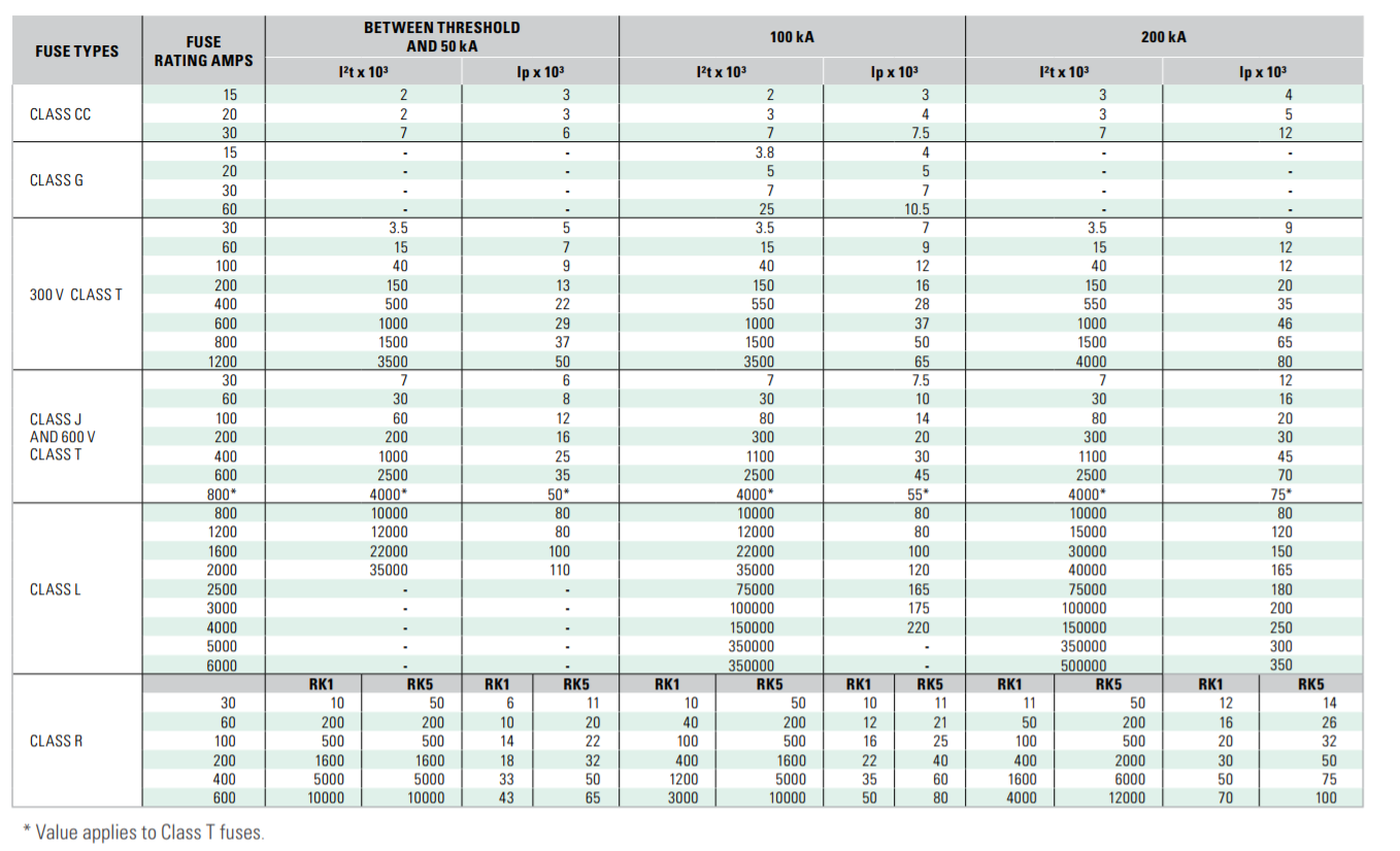
Figure 2: UL maximum allowable Ipeak and I2t values for various types of fuses (Source: Littelfuse 2010)Determining the available short circuit current allows for proper fuse selection within the entire system. Knowing how much current a fuse will let through during a fault current situation helps engineers design safe electrical panels, while at the same time protects connected equipment from fire.
The primary role of the fuse is to prevent equipment fire, not to protect the equipment itself from damage. The available short circuit current at a given point in the electrical system can be determined by reviewing the components which are upstream from the electrical supply point.
Direct Feed Requirements
The SCCR rating of the motor control system is determined by examining the maximum ratings of the individual devices connected to the individual branch circuits. The device with the lowest rating becomes the limiting factor.
Figure 3 below shows an example of a branch circuit diagram fed by a 460V three phase supply.
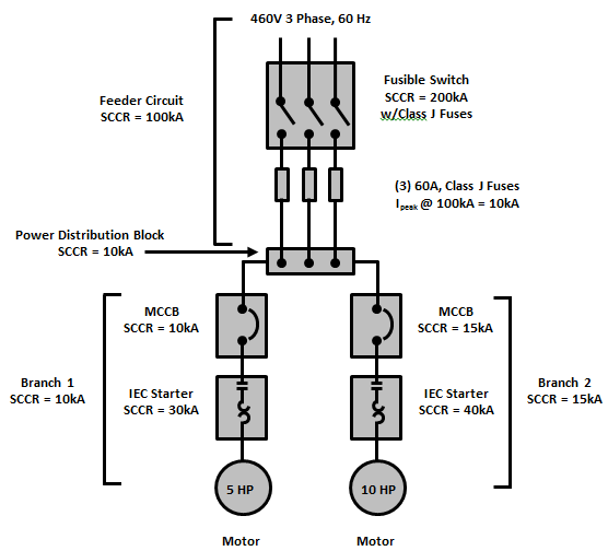
The SCCR of Branch 1 is 10kA due to the SCCR value of the molded case circuit breaker (MCCB). Whereas the SCCR of Branch 2 is 15kA resulting from the MCCB. Therefore, Branch 1 is the limiting factor. This motor control system can be fed by a circuit having a maximum capacity of 10kA.
The feeder circuit is comprised of a fusible switch having a rating of 200kA which is intern connected to a distribution block having only a 10kA rating. Therefore, the distribution block limits the combination to a 10kA rating for the feeder.
However, the fuses which are placed in the fusible switch can be selected such that they limit the available peak current. The combined FLA of the system requires a 60A fuse. As an example, selecting an RK5 60 amp fuse would limit the peak let-through current to 21kA when connected to a system capable of 100kA as defined by Figure 2.
However, this is 11kA more current than what the branch circuits are capable of handling.
A better choice would be a Class J fuse with a peak let-through current of only 10kA. Using the 60A Class J fuse, the available peak current on the load side of the fuse is only 10kA, which then satisfies the 10kA limitation of the distribution block and the MCCB in Branch 1. The result is that the complete system can be connected to a supply having a 100kA rating.
It is important to note that fuse manufacturers often publish lower peak let-through values for their fuse products than what is listed in the UL table in Figure 2. However, when designing the distribution system, the UL values must be utilized rather than the manufacturer specific values as these are considered worst case.
AC motor control systems being fed by an isolation transformer, the fuse type and size is dictated by the available short circuit current of the isolation transformer. To select the proper fusing, the available short-circuit current of the transformer must first be determined.
Feeders with Isolation Transformers
Maximum permissible fuse sizing is dictated by UL and further by the National Electric Code, NEC. According to the National Electric Code (NFPA-70 or CSA 22.1), per Article 450-3(B) of NFPA-70 (similar statements can be found in CSA 22.1), the maximum fuse size is defined in table 450.3(B) with a rating not greater than 125% of the rated secondary current.
In the case of multiple secondaries, it is the rated value of the winding with which the unit is supplied from. The fusing of the transformer supersedes the fuse rating of the AC motor control; because the value required for the transformer is often lower than the maximum value the AC motor control was tested with.
One more step must also be taken to ensure proper fuse selection. An isolation transformer limits the available short circuit current of the system. With a limited available fault current, the peak current may not be enough to clear the fuse in a fault situation.
For adequate protection, the fuse must clear instantly, with the upper clearing time limit within the first half cycle of an AC current wave (i.e., approximately 10mSec). Therefore, it is necessary to determine the amount of short-circuit current available on the secondary winding of the isolation transformer.
Sizing Example
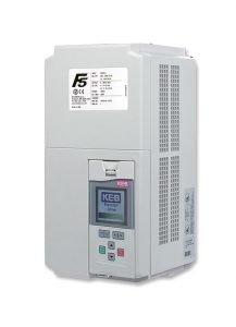
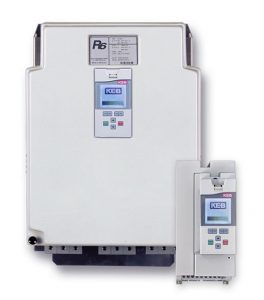
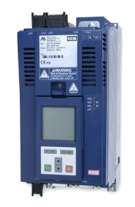
Consider the following example for proper fuse sizing. A 460V application is using an isolation transformer rated for 34kVA, a KEB Harmonic Filter, KEB R6 regen unit and KEB F5 elevator drive.
Since the available short circuit current of the isolation transformer is unknown, it must be calculated. To calculate the transformer secondary rated current, along with the collective available short circuit current, the following equations can be used…
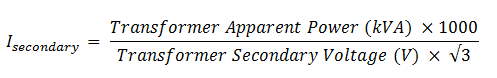
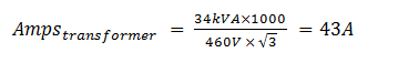
The secondary current can be calculated using the 34kVA power rating of the isolation transformer fed with a 460V line. Equation (1a) becomes the following…
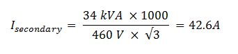
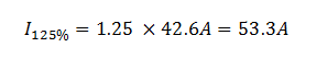
The fuse size must not be greater than 125% of the secondary rated current. From the Eq. (2) below, 125% of the secondary rated current is 53.3 amps.
Next, the available short-circuit current at the transformer must be determined. This can be calculated by determining the collective available short circuit current.
Collective Short Circuit Current
To protect against short circuit currents, limited by an isolation transformer, the required current a fuse needs to clear instantly needs to be evaluated. To do this, the collective available short circuit current of the mainline and isolation transformer must be determined.
Table 2 below provides a summary of the short-circuit current calculations followed by detailed calculations for determining the available short circuit current of the isolation transformer.
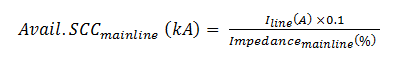
To calculate the available short circuit current of the mainline and transformer, the following equations can be used.
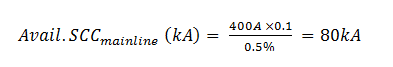
Assuming the mainline has a current of 400 amps and an impedance of 0.5% Eq. (3a) becomes the following…
Next, the current of the transformer can be calculated by the following equation…
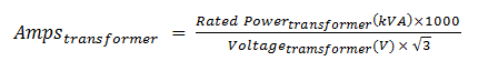
Assuming the transformer has a rated power of 34 kVA Eq. (4a) becomes the following…
Next, the available short-circuit current of the transformer can be calculated by the following equation…
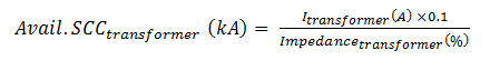
Assuming the transformer has a rated impedance of 5% and a current of 43 amps Eq. (5a) becomes the following…

Now that the available short circuit current of the transformer has been calculated, the proper fuse must be selected. To select the proper fuse size, consult with the manufacture’s published fuse blow curves.
Fuse Blow Curves
Fuse manufacturers typically publish self-tested performance data for their fuses to help customers select the proper size. This performance data typically varies between manufacturers, so be sure to consult the manufactures’ data before selecting a fuse.
For this application, Class J fuses are to be used. Figure 4 below shows the performance data for Mersen Time Delay Class J fuses (Mersen Electrical Power, 2002).
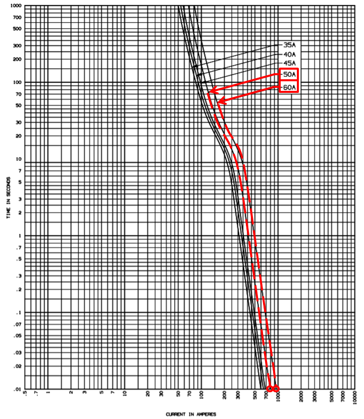
Figure 4: Time Delay Class J Fuse Melting Time – Current Curve (Source: Mersen Electrical Power, 2002)Figure 5 below shows the performance data for Mersen High-Speed Class J fuses (Mersen Electrical Power, 2003).
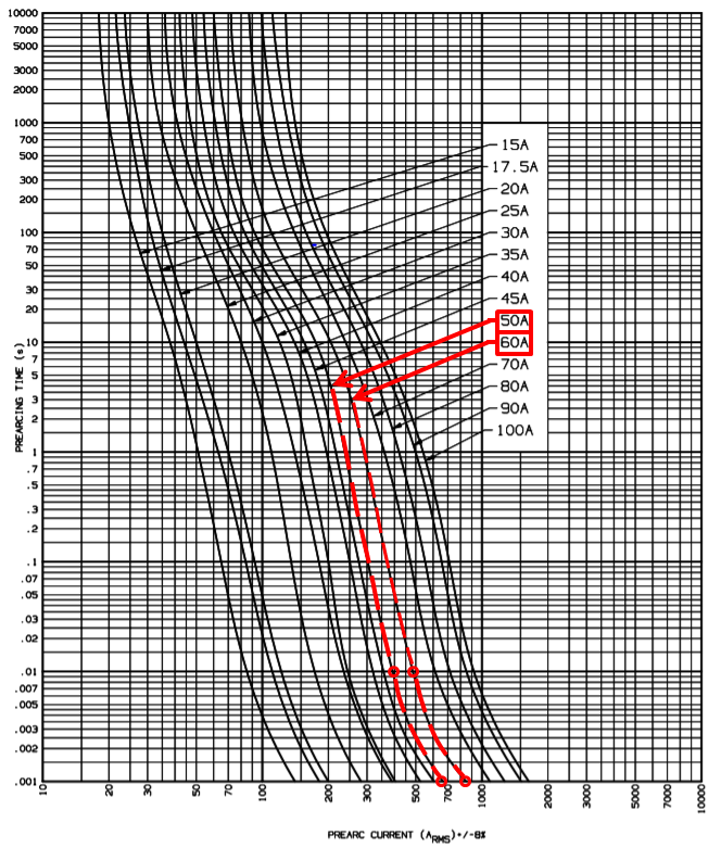
Looking at the Figure 4, Time Delay Class J Fuses rated for 50A and 60A require 800A and 950A, respectively, for 10ms to clear. In comparison, as seen in Figure 5, High Speed Class J Fuses rated for 50A and 60A require 400A and 500A, respectively, for 10ms to clear.
The Time Delay Class J fuses do not provide adequate short-circuit protection as the available short-circuit current may not be high enough to clear the fuse within one-half cycle and therefore should not be used in this application. The High-Speed Class J fuses are a much safer option by providing the required clearing currents down to 1ms According to Figure 5, the 50A and 60A fuses require 675A and 850A, respectively, for 1ms to clear.
Recall that the available short circuit current from the isolation transformer is 860A. The 60A High Speed Class J Fuse is marginally close, (850A) to the available short circuit current from the isolation transformer (860A). Given this information, the 50A High Speed Class J fuse is the best choice to provide adequate short circuit protection.
For the best protection of electrical components, KEB recommends using Mersen High Speed Class J fuses. These fuses can take the place of a standard Class J fuse; however, they perform like a semiconductor fuse.
If you’d like to learn more about KEB control and automation solutions, you can reach us through the Contact Us page or complete the form below.
Sources
Figure 1: Littelfuse. (2010). AC current waveform behavior after a short circuit fault. [Digital image] Retrieved Sept. 17, 2017.
Figure 2: Littelfuse. (2010). UL maximum allowable Ipeak and I2t values for several types of fuses. [Digital image] Retrieved Sept. 17, 2017.
Figure 4: Mersen Electrical Power. (2002). High Speed Class J fuse melting time – Current curve. [Digital Image] Retrieved Sept. 17, 2017.
Figure 5: Mersen Electrical Power. (2003). High Speed Class J fuse melting time – Current curve. [Digital Image] Retrieved Sept. 17, 2017.
Related Articles
Let's Work Together
Connect with us today to learn more about our industrial automation solutions—and how to commission them for your application.