
VFD Braking Resistor Protection and Monitoring Short Circuit Failures
KEB introduces a new safety feature that allows the F5 Elevator drive to monitor for short circuit failures within the drive’s braking transistor. When properly connected, this internal monitoring board can prevent external damage to braking resistors that can pose a fire hazard if overloaded. The internal monitoring board is standard on all G, H, R, and U housing F5 Elevator drives.
What are Braking Resistors?
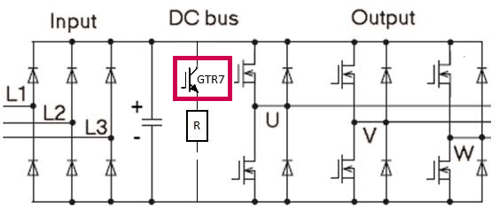
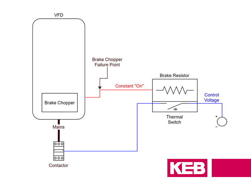
Braking resistors are connected in series to the drive’s braking transistor (GTR7), which is connected to the DC bus and is typically sized for intermittent duty; not continuous. If the drive’s braking transistor fails with a short circuit, the external braking resistors will have constant current flow through them via the drive’s DC bus. This can result in damage to the resistors as well as create a fire hazard.
Braking Resistor Protection
To properly protect the braking resistor during a VFD braking transistor short circuit, power must be removed from the braking resistor or VFD itself. This is typically done by placing a contactor between the VFD and the braking resistor or in front of the drive’s input.
Difficulties with Temperature Monitoring
This contactor can be controlled by a temperature monitoring circuit on the dynamic braking resistors. During a braking transistor short, the resistors will become directly connected to the VFD DC bus and begin to heat up, triggering the temperature monitoring circuit, which then opens the contactor. While this method is effective it can cause entrapments and is prone to nuisance trips if the temperature circuit is not properly calibrated. The resistors must heat up before the temperature sensor triggers, which could pose a hazard.

Internal Braking Transistor Monitoring
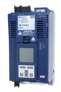
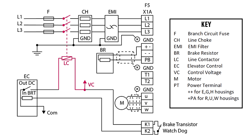
KEB’s internal braking transistor monitoring board (Figure 2) eliminates the need for a temperature monitoring circuit on dynamic braking resistors. When a braking transistor short is detected, the drive will open a normally closed pilot contact labeled K1/K2. The K1/K2 terminals can be connected to the elevator controller, which can be programmed to monitor the state of the contact and determine how to respond. If a short circuit is detected during a run, the controller can respond by finishing the run, letting passengers out, opening the contactor, taking the car out of service, and preventing an entrapment. The drive will not display a fault if the braking transistor has shorted. The elevator controller, for proper implementation, must monitor the K1/K2 contact.
Options for Cutting Power During a Failure
Power can be removed from the braking resistors during a braking transistor failure in one of two ways.
Option 1 – Disconnecting Braking Resistor Only
The first option allows only the braking resistor to be disconnected from the drive circuit. This is accomplished using a DC contactor between the drive and braking resistors. When a failure occurs, the controller can open the contactor; thus stopping current flow through the resistors.
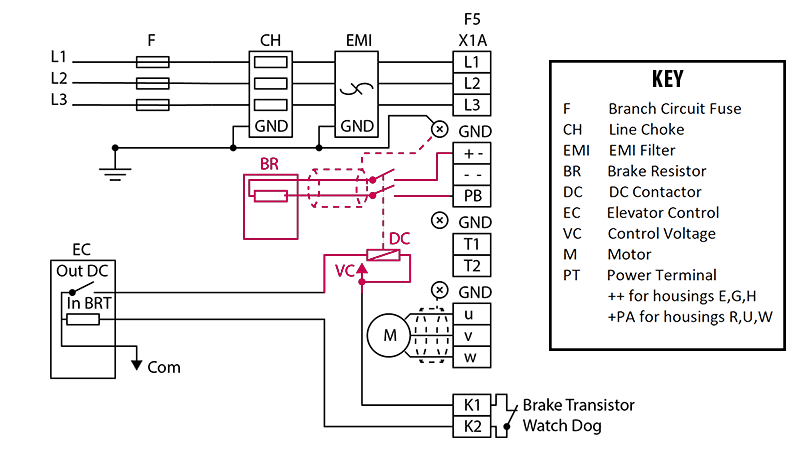
Option 2 – Disconnect Supply Voltage to the Drive
The second option disconnects the incoming supply voltage to the drive. In Figure 4, the controller can open a line contactor connected between the supply voltage and the drive’s input; thereby cutting power to the drive. Again, if the failure occurs during travel, the controller will bring the car safely to the floor before shutting down.
Braking Transistor Monitoring Solution
KEB also offers a braking transistor monitoring board that can be externally mounted in the control cabinet. This solution is useful for existing jobs that do not feature the internal monitoring board and for the smaller D/E housings of the F5.
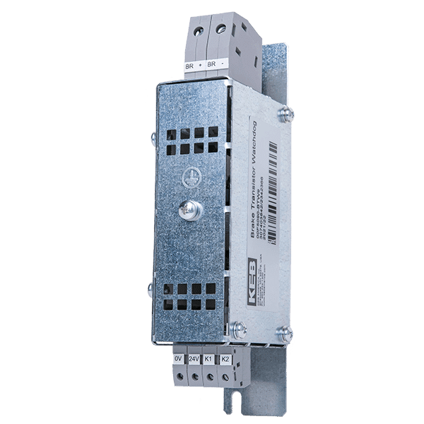
The principle of operation and control schemes are the same. The module is connected between the controller and the drive. The drive can supply power to the module via its 24VDC supply or an external 24VDC supply. The module’s BR+/BR- terminals are connected across the drive’s braking transistor terminals at ++ and PB to monitor the braking transistor. An external terminal block is required to accommodate the braking resistor and BR+/BR- module connections. The controller can again connect to the K1/K2 terminals on the module and can control the external contactor in the chosen control scheme.
Contact KEB for more information on braking transistor monitoring and how to protect braking resistors properly.
Brian Holtzkamp is an application engineer in the elevator group at KEB America. He has been with KEB since 2008; previously serving in KEB’s service and repair department. He has an Associate’s Degree in Electronics from Hennepin Technical College, Minneapolis, MN.
This article is also found on Elevator World’s website and magazine.
Related Articles
Let's Work Together
Connect with us today to learn more about our industrial automation solutions—and how to commission them for your application.