
While much attention is paid to the power that the VFD outputs and the built-in functions to protect the motor, the functions built around the power to the drive are just as important. KEB drives have protection functions that protect them from issues with the main line power supply. These allow the machine designer to know the VFD is protected from the occasional loss of phase or power spike.
Over/Under Voltage Protection
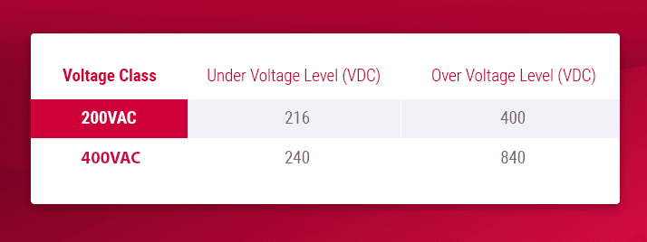
The drive’s first and most basic function to protect itself is the under/over voltage errors. When supplying an AC supply to the drive, it rectifies that to a DC voltage. The resulting DC voltage will be ~1.41x the AC supply. So, for a 480VAC supply, the DC voltage will be ~675VDC. This DC voltage is then measured, and the drive will trip into an error if it goes too low or too high.
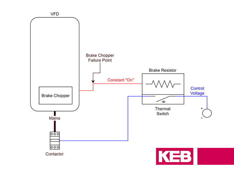
Related Article: VFD Braking Resistor Protection and Monitoring Short Circuit Failures
VFD Power Monitoring – Supply Issues
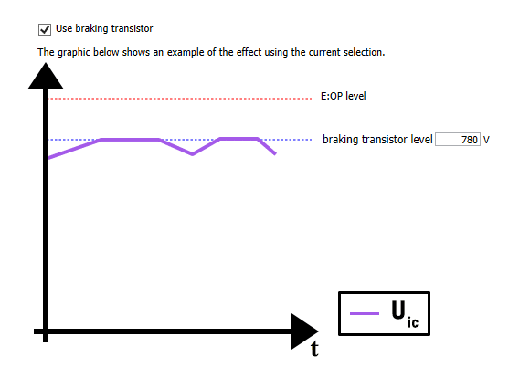
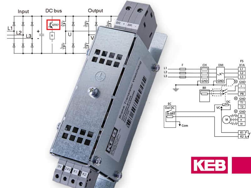
Under voltage errors are typically a power supply issue, and little can be done on the VFD side for troubleshooting. An example would be sagging mains when other machines turn on because the power supply to that branch is too small. Over voltage errors can also be a power supply issue, but they can also be a programming/machine design issue. The latter will be the case if the error is repeatable when the motor decelerates or is overhauling. The motor functions like a generator in these operations, sending energy back toward the VFD. The energy causes the DC bus voltage to rise, eventually leading to overvoltage errors. To prevent errors in these situations, the deceleration time needs to slow down, the speed/load needs to be reduced, or the energy needs to dissipate. This can be achieved by adding a braking resistor or regen unit to the circuit. The under and overvoltage errors are simple but are essential to ensure the drive has the proper power supply.
Monitoring for Loss of Input Phase
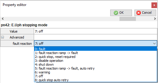
The next function also monitors the DC bus voltage, but it is slightly more complex in how it works. It is the E.Uph or input phase detection error. It includes two functions designed to avoid pre-mature aging of the drive’s capacitors. The first is always active and is triggered if the ripple of the DC bus voltage exceeds a set value a certain number of times. An imbalanced or missing leg typically causes a higher ripple on the three-phase AC supply. The second of the two E.Uph functions are programmable with the parameter pn.42. This function also monitors the ripple of the DC bus voltage, but only within a specific frequency range. However, since this ripple can be triggered by application-specific factors such as load cycling or oscillations of the controller, this monitoring function can be switched off or give a warning instead of an error. Both input phase failure detection functions are designed to protect the drive from imbalanced or missing phases, which are signs of poor power quality into the drive.
What is UPS Mode in a VFD?
The final function built around the power supply to the drive is the Uninterruptable Power Supply (UPS) mode. The UPS mode allows the VFD to be switched onto a UPS system with a lower voltage than the typical mains voltage in the event of a mains failure. It allows for emergency operation without the UPS system causing an under-voltage error. An example of this functionality is an elevator moving so that trapped passengers can get out while the power to the building is down. The UPS function is a crucial protection function when power is lost to the drive.
Conclusion
By monitoring the DC bus voltage, these functions combine to allow the drive to protect itself, the motor, and the application from issues caused by the input power to the VFD. Contact a KEB Application Engineer to apply these functions to your application!
Related Articles
Let's Work Together
Connect with us today to learn more about our industrial automation solutions—and how to commission them for your application.