
Some industrial automation machines can encounter induction motors driving high inertia loads running at high operational speeds. Slowing and stopping these large loads can prove difficult at times. Once power is removed from the induction motor, the motor may slowly coast until a standstill is reached.
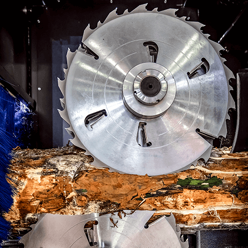
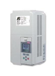
For example, a customer has a VFD driving a circular grinding wheel. The wheel has a high inertia and turns at high speeds, such that when the wheel is turned off, it takes a few minutes before the wheel comes to a stopped position. Due to safety concerns and production downtime, the customer would ideally like to stop the wheel in a quicker fashion. One function that would help the customer here is DC injection braking, which is found in our F5 VFD and S6 Servo Drive products.
What is DC Injection Braking?
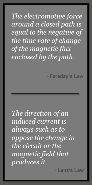
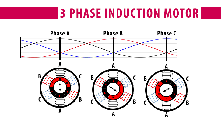
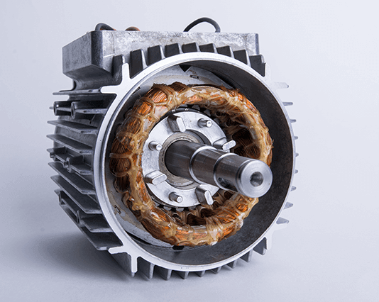
Three-phase AC induction motors operate by receiving three-phase AC power input to the stator windings. This three-phase power creates a rotating magnetic field in the stator windings. This rotating magnetic field induces a voltage (EMF) and associated current in the squirrel-cage rotor due to Faraday’s Law. This induced current creates its own magnetic field that opposes the relative motion of the rotating magnetic field per Lenz’s Law. This electromagnetic induction and opposing magnetic fields is what causes rotation and torque to be produced at the motor shaft.
If the three-phase AC input is removed from the motor stator, the rotating magnetic field will be removed and the electromagnetic induction process will cease. The motor shaft will then coast to a stop. For high inertia loads or loads spinning at high speed, the motor shaft can take a considerable amount of time to reach a stopped position. These high inertia loads can include fans, centrifuges, and saw blades.
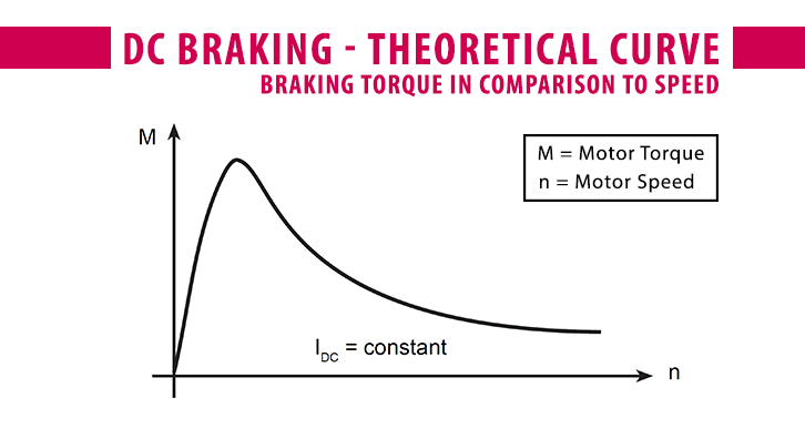
DC injection braking, or DC braking, is the process of injecting direct current (DC) into the stator windings of the AC motor. DC braking is able to provide a rapid and controlled stopping of a motor load. Once the AC input is removed from the motor, a DC current is applied to the stator which creates a stationary magnetic field inside the stator windings. The rotating rotor then begins to cut the magnetic field lines of the stationary magnetic field, thus inducing perpendicular, swirling eddy current in the rotor due to Faraday’s Law. This induced current then produces its own magnetic field to oppose the stator’s stationary magnetic field per Lenz’s Law. This opposing magnetic field in the rotating rotor creates a braking torque that quickly decelerates the rotor and load. The strength of the braking torque is proportional to the amount of DC voltage and current applied to the stator windings. The greater the DC current on the windings, the greater the strength of the stationary magnetic field, and thus, the greater the braking torque applied to stop the load.
This electromagnetic phenomenon is similar to eddy current braking which is found on many amusement rides and electric passenger trains.
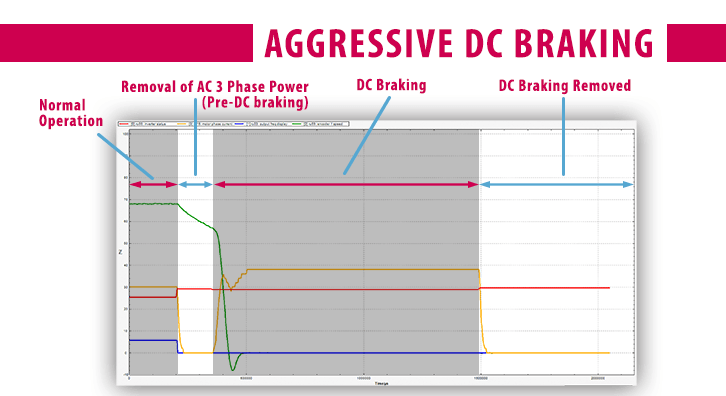
Green = motor speed
Yellow = motor phase current
Red = Inverter Status
Blue = Output frequency
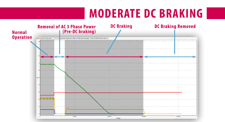
Combivis 6 Scope of Moderate DC Braking Profile
Green = motor speed
Yellow = motor phase current
Red = Inverter Status
Blue = Output frequency
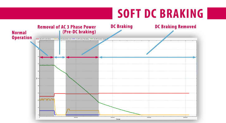
Combivis 6 Scope of Soft DC Braking Profile
Green = motor speed
Yellow = motor phase current
Red = Inverter Status
Blue = Output frequency
DC injection braking employs the use of electromagnetic induction to decelerate a moving motor. From the laws of induction, a change in flux (or, the amount of magnetic field through a surface) is necessary to induce electromotive force (EMF). Therefore, if the rotor is at a zero-speed position, theoretically, the EMF or braking torque on the rotor will be zero. However, if attempting to move the rotor shaft from a stopped position while DC current is supplied, the slight movement of the rotor will again induce current and an opposing magnetic field, which will try to slow the rotor to match the stationary magnetic field. As will be discussed below, DC braking should only be used to quickly decelerate a load, and is not able to statically hold a load.
DC Braking with a KEB VFD
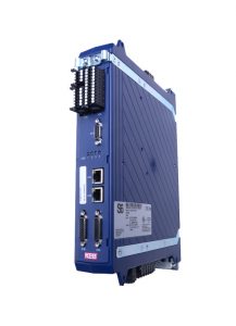
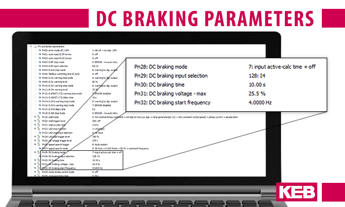
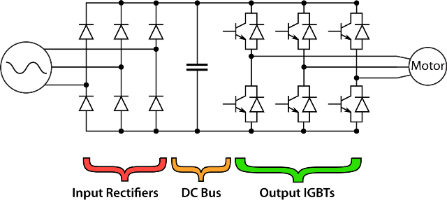
DC braking is available for three-phase AC induction motors using KEB F5 and G6 drives under V/Hz or ASCL operating modes. KEB offers 9 different DC braking modes that are programmable based on 5 protection parameters. The programmable DC braking parameters include; braking mode, braking input selection, braking time, maximum braking voltage, and braking start level/frequency. Depending on how these parameters are set, the DC braking function can be automatically initiated once rotation direction is removed, triggered once a specified speed is achieved, or, the braking function can require an input be activated. For most operations, once the DC braking process is initiated, the AC three-phase modulation will immediately switch off. Then, the DC current and voltage will be injected into the stator windings from the DC bus of the KEB VFD, starting the rotor deceleration.
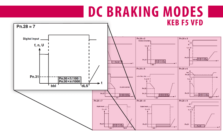
For an open-loop KEB drive such as a G6 Open-Loop VFD or F5-Compact, the default parameters in the drive are situated for DC braking capability right out of the box. DC braking mode 7 is setup as the default, which uses the braking input selection, time, and maximum voltage parameters. Programmable digital input 4 is programmed as the DC braking input selection. For default settings, if that digital input is made active, DC braking will only occur for a brief calculated time and then the VFD will remain in a stopped position. Only once the DC braking digital input is deactivated will regular drive operation continue.
Advantages and Limitations of DC Braking
DC braking utilizes the VFD’s own DC bus to inject DC current and voltage into the stator windings. Therefore, no additional components or materials are necessary for braking action. Friction braking requires a separate electromagnetic brake module to be mounted within the system, and requires eventual service and replacement due to the wear of components. With DC braking, no friction contact is made so the service and replacement of components is minimized.
Another advantage of DC braking is the mitigated risk of regenerative energy and over-potential (E.OP) faults. When trying to quickly decelerate a high inertia or high speed load using a fast deceleration ramp, you run the risk of regenerative energy being put back into the drive. This will likely cause an over-potential (E.OP) fault in the drive. With DC braking, a quick braking action is still achieved, but the braking energy is transferred into the motor, and thus no regenerative energy is reflected back to the drive.
The main limitation with DC braking is heat. Applying a DC current into the stator windings is similar to a short circuit between the windings, so it is imperative that DC braking only be applied for a few seconds to avoid overheating the motor. Also, the energy produced during the braking process is absorbed by the rotor as heat, so this is another thermal consideration.
If DC braking is to be used frequently, this must be taken into account when sizing the VFD and motor. Motor thermal protection is also recommended for applications using DC braking.
DC braking is designed for decelerating a load, not holding or supporting a load. Due to electromagnetic induction and the aforementioned thermal considerations, DC braking should not be used to statically support a load.
Since VFD power is required for DC injection braking, DC braking is not considered a fail-safe braking method and should not be relied upon for stopping a machine in case of emergency.
DC braking is NOT considered a fail-safe braking method and should NOT be relied upon for stopping a machine in case of emergency.
Conclusion
DC injection braking is an efficient and effective way to rapidly decelerate a high inertia load. No external components are necessary, so DC braking can be easily implemented in your application today.
Are you interested in learning more about DC injection braking? If so, please use the form below to discuss with one of our application engineers.
Related Articles
Let's Work Together
Connect with us today to learn more about our industrial automation solutions—and how to commission them for your application.