
VFD Storage and Capacitor Reforming
For production and manufacturing atmospheres, a machine down can be a painful event. In this article, we cover proper VFD storage and capacitor reforming to make the situation a bit easier on you and your customers.
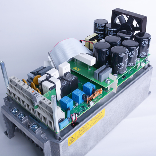
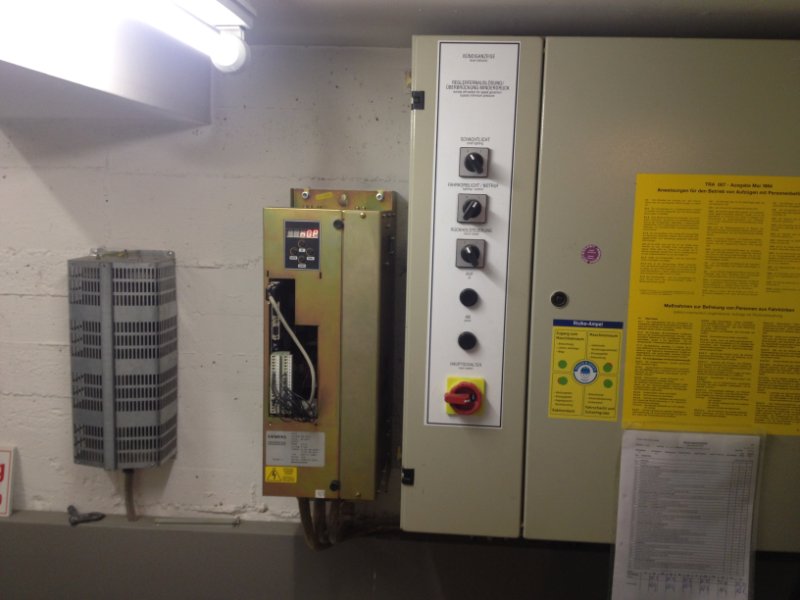
Let’s start with an example – a manufacturing facility has a few large machines that are critical to daily production and operation. One of these machines goes down and it is determined that the variable frequency drive (VFD) within the machine has failed or needs to be serviced/repaired. Ordering a new drive or having the drive serviced/repaired is expected to take approximately four weeks. The manufacturing facility cannot accept this downtime on their machine. Fortunately, the manufacturing facility has an easily accessible spare drive-in storage specifically for this situation. Instead of undergoing the lead time of a repair or new order, they plan to install the stored spare drive.
After getting the four-year-old drive out of storage, removing any remaining packaging materials, and blowing the dust off of the unit, the user installs the proper inputs/outputs and attempts to run, but the drive fails upon power-up. The electrolytic capacitors within the VFD have slowly lost their internal oxide layer and the sudden input of rated voltage has destroyed the capacitors. Now, the manufacturing facility has two failed VFDs and they are now facing a four-week lead time.
What is an Electrolytic Capacitor?
A capacitor is an electrical device that stores electric charge and is constructed using two conductive materials separated by an insulating dielectric layer.
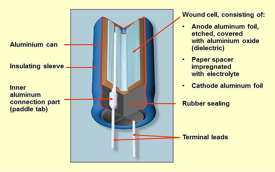
An electrolytic capacitor is a form of polarized capacitor device that uses a metallic plate (commonly aluminum or tantalum) as the anode. The conducting anode forms an external oxide layer that represents the insulating dielectric material. A second metallic plate serves as the negative electrical connection for the capacitor, but between the dielectric oxide layer and this second metallic plate is a paper material that is soaked in liquid electrolyte. This paper material soaked in electrolytes serves as the physical cathode for the electrolytic capacitor. These metallic plates (named the anode foil and cathode foil) and electrolyte-soaked paper are typically foiled materials, so very low thickness, and are wound together inside an aluminum can covered in an insulating sleeve.
There is also typically an electrolyte-soaked paper on the outside of the cathode foil. Electrolytic capacitors normally have a larger capacitance value than other types of capacitors, and a leading factor of the capacitance value is the surface area of the anode foil. A process called etching is a specialized surface roughening procedure of the anode foil that induces a higher surface area and thus, a greater capacitance value.
The dielectric oxide layer is initially formed on the etched surface by applying a positive voltage to the anode foil in an electrolytic bath. This forms a dielectric oxide layer on the anode foil with a thickness that correlates to the applied voltage. During normal operation, when DC voltage is applied to the capacitor, the dielectric develops a magnetic field which creates a polarized charge between the two electrodes.
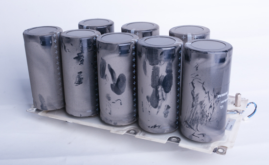
The dielectric oxide layer does contain imperfections and there is potential for current to leak through the dielectric after applying DC voltage at the correct polarity. This leaking current due to imperfections is called the leakage current. Since the oxide layer is formed by applying rated voltage to the anode, when the capacitors sit in storage without externally applied voltage for some time, the dielectric oxide layer starts to deteriorate. Without voltage, this dielectric oxide layer reacts with the acidic electrolyte and the oxide layer starts to break down. As the dielectric layer starts to deteriorate, there will be a large leakage current that will flow when rated voltage is applied. This high leakage current flowing through the capacitor with the deteriorated dielectric can destroy the capacitors.
Fortunately, aluminum electrolytic capacitors have self-healing characteristics and the dielectric layer can be rebuilt under a process called “capacitor reforming.”
KEB Capacitor Reforming Process
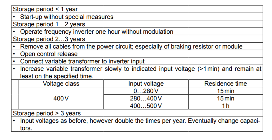
KEB has a suggested practice for how to reform VFD capacitors given a certain amount of non-powered storage time. These storage reforming procedures are found in the respective power stage manual for each VFD housing size.
The longer a VFD sits without external power, the more rigorous the reforming of the capacitors.
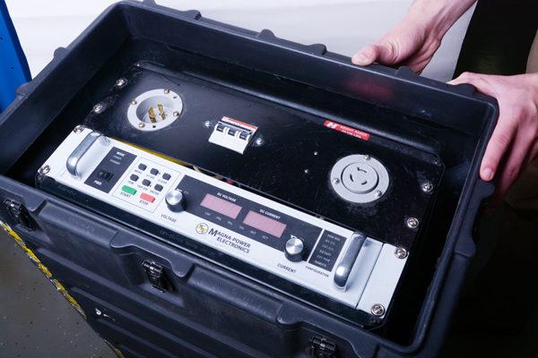
For example, for a KEB R-housing drive, for storage of under one year, the drive can be started without any special measures. Once an R-housing drive has been in storage for over one year, special reforming procedures are recommended and should be followed. Between 1-2 years of storage, the VFD is to be operated for one hour without any modulation output. Any time after two years of non-powered storage duration will require the use of a variable transformer to control the input and slowly increase the voltage to the VFD.
The actual storage time for a particular KEB drive may be longer than the time it has been stored on your shelf. For example, the time that a drive is in transit or sitting at another facility also adds to the current storage time of the drive. Therefore, it is best practice to utilize the VFD nameplate and locate the manufactured date code to determine when the drive was actually produced. This way, you can create a better understanding of how long the drive has likely been in storage.
*Disclaimer: These procedures are recommended for KEB VFD products ONLY. If you are using a different brand of VFD, you should always check and consult the manufacturer’s suggestions on storage and reforming.
During reforming, leakage current decreases within a short time after applying DC voltage. During this time, the oxide layer can be regenerated and the leakage current will begin gradually declining to its normal level.
What is the best practice for stored drives?
Looking back to the example with the manufacturing facility, what could they do differently to properly utilize stored VFDs?
The best practice would be to take all the drives you have in storage and power them up regularly (approximately every six months) with rated AC Voltage to reform the capacitors and ensure correct VFD operation. This way, you will limit your need for special reforming procedures and avoid destroying your capacitors.
Contact Us
If you have any questions regarding the capacitor reforming procedures, or what you should do for your specific stored KEB drive(s), please reach us using the Contact Us form.
Sources
https://en.wikipedia.org/wiki/Capacitor
https://en.wikipedia.org/wiki/Aluminum_electrolytic_capacitor
http://www.capacitorguide.com/electrolytic-capacitor/
https://de.tdk.eu/download/185386/5f33d2619fa73419e2a4af562122e90c/pdf-generaltechnicalinformation.pdf
Related Articles

Let's Work Together
Connect with us today to learn more about our industrial automation solutions—and how to commission them for your application.