
How Do I Size a Motor for My Application (Rotary Index Table)?
A popular question that we hear is, “How do I size a motor for my application?” This post looks at an example Rotary Index Table application and provides the equations and considerations needed to make the appropriate motor selection.
1. Gather application info and define the Move Profile
First, consider your machine’s movement. In our sample case of a Rotary Index Table, an engineer will need to first define all relevant information that will be used later in the Torque calculation. Typical information we will need includes:
- X = rotational move distance (radians)
- tmove = Total move time (sec)
- tdwell = Dwell time between move
- tcycel = tmove + tdwell
- ta = acceleration time (sec)
- td = deceleration time (sec)
- ωmax_index = peak angular velocity (rad/sec)
- mindex_table = mass of index table (lbs)
- rindex_table = radius of index table (in)
The move profile will define the required move distance along with the time for acceleration, constant run, deceleration, and the dwell time between cycles. The velocity move profile can take on a triangular or trapezoidal shape as shown below. For this exercise, we will assume there is no s-curve to smooth the transition points.
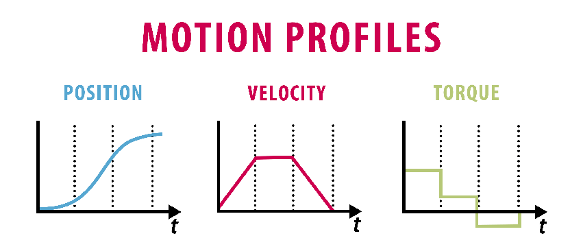
The move profile can indicate a linear or rotational movement. The total area under the velocity curve defines the total move distance. Utilizing the data from the move profile will allow us to define the required maximum output speed of the motor.
2. Define the Maximum Rotational Speed
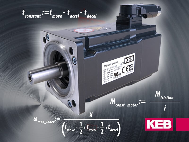
The maximum required output rotational speed to make the move in the given cycle time is:

Converting the angular velocity to RPM, we can define the maximum rotational speed rpmmax_index
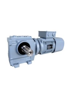
If a gearbox is used, the gearbox ratio, i, can be used to define the maximum motor speed.
rpmmotor_max = rpmmax_index * i.
If no gearbox is used, then i = 1.
3. Calculate the Acceleration of the Motor
Since we want to define the required motor torque, we want to be sure that we are using values that pertain directly to the motor itself. If there is a gearbox in the system, we need to be sure to reflect the required values back to the motor. We will need to determine the acceleration torque, deceleration torque, constant torque, and any torque due to gravity on the system. For this exercise, we will assume the index table is in a horizontal position, so the torque due to gravity will be zero.
Using the maximum angular velocity and deceleration times, we can calculate the angular acceleration, αaccel_motor and angular deceleration, αdecel_motor.
We are assuming the system starts and stops at 0 speed.
αaccel_motor = (ωmax *i)/taccel
αdecel_motor = (ωmax *i)/tdecel
4. Calculate the Inertia of the System
Once we know the angular acceleration of the motor, we need to calculate the inertia of the load connected to the motor. In this case, we can approximate the index table inertia using the formula for a solid cylinder.
Jindex_table = ½*mindex_table*rindex_table2
Where
mindex_table = mass of index table (lbs)
rindex_table = radius of index table (in)
The load on the index table must also be taken into account. If the load is distributed evenly over the indexed surface, we can add this load into table weight to calculate the inertia of the complete system. If the load is not distributed evenly, then a separate load inertia will need to be determined, Jload.
If there is a gearbox in the system, this inertia is reflected back to the motor shaft by the square of the gearbox speed reduction ratio.
Jreflected = (Jindex_table + Jload)/i2
5. Calculate the Required Torque
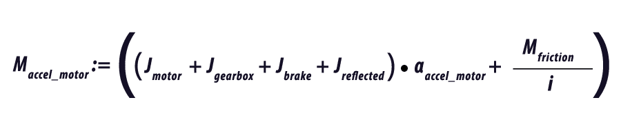
Now that we know our inertia and our acceleration and deceleration rate, we can determine the required torque. If known, we can add in the inertia of the motor, Jmotor, the gearbox, Jgearbox and a brake on the motor, Jbrake, if the system has a brake.
Depending on the design of the system, there may be a constant friction torque, Mfriction, which must also be accounted for in the motor sizing. The amount of this constant torque will be dependent on the friction coefficient of the system and the weight of the table and load. Again, if there is a speed reduction in the system we can reflect this back to the motor shaft.
We can calculate the required torque for each of the operating sections of the move profile. The acceleration (Figure 2), constant run (Figure 3), and deceleration (Figure 4).


Note that the friction torque helps to slow the system. This can be used to allow the time to decelerate the system to be reduced and the time to accelerate the system increased. This has the advantage of decreasing the peak torque requirement of the motor. If the application allows a faster deceleration time, this may allow the motor size to be reduced.
The above values will give the peak-required torque to complete the move profile. The motor must have the capacity to provide this torque.
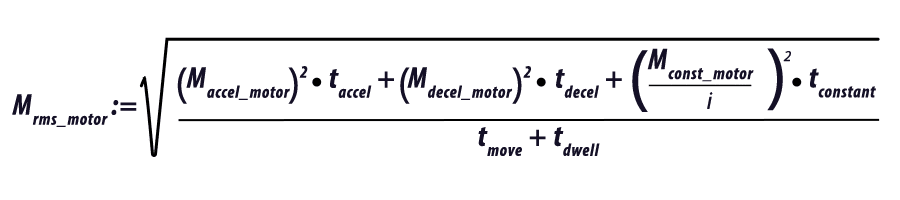
In addition to determining if the motor has sufficient torque to make the move as defined by the move profile, we must also verify the rms motor torque over the complete cycle is less than or equal to the rated torque of the motor. If the rms torque is higher than the rated torque of the motor, the motor may overheat.
To calculate the rms torque over the cycle, we need to know the dwell time between cycles, tdwell, and the constant run time of the move profile if it is a trapezoidal move.

6. Make Motor Selection
Optimizing the motor sizing for an indexing application can be an iterative process. By calculating the peak requirements and rms torque of the application, the selection of the motor can be done with confidence to provide a reliable solution for the application (see Figure 7).
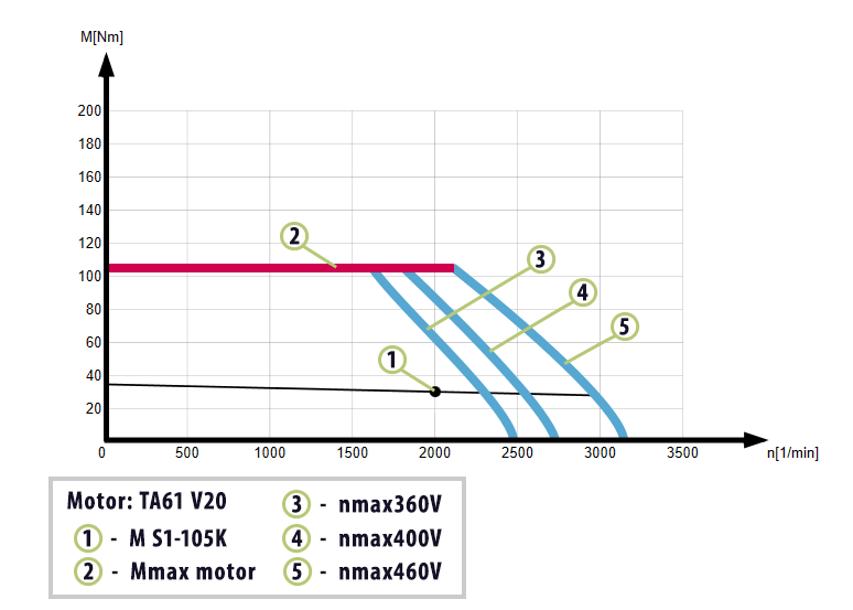
In our example, we would want to make a motor selection that offers rated torque above the calculated rms torque value across the needed speed range. Additionally, we would want to make sure the peak torque (red line) is more than the calculated maximum torque value.
KEB – Helping Make Better Machines
Do you have questions about choosing the correct motor size and technology for your application? Contact a KEB Engineer today to discuss your machine design.
Related Articles


Let's Work Together
Connect with us today to learn more about our industrial automation solutions—and how to commission them for your application.