
How Pulse Width Modulation in a VFD works
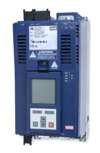
Variable frequency drives (VFDs) used on industrial applications provide an efficient way to vary the speed and torque of the connected motor. The VFD consists of three main parts: The input converter section, the intermediate DC bus, and the output inverter section.

The converter section uses a diode bridge rectifier to convert the AC input voltage to a DC voltage. The DC bus section consists of a capacitor bank, which is used to smooth out the DC voltage from the converter section and provide some voltage storage capacity. The inverter section of the VFD takes the DC voltage from the DC bus and inverts it back to a variable voltage and variable frequency AC voltage used for the motor control.
What is Pulse Width Modulation (PWM)?
The process involved in inverting the DC voltage to the variable voltage variable frequency (VVVF) AC voltage in the inverter section of the VFD is called pulse width modulation or PWM.
Pulse width modulation uses transistors that switch the DC voltage on and off in a defined sequence to produce the AC output voltage and frequency. Most VFDs today utilize insulated gate bipolar transistors or IGBTs. The typical configuration of the IGBTs in the inverter section of a VFD is shown below in figure 2.
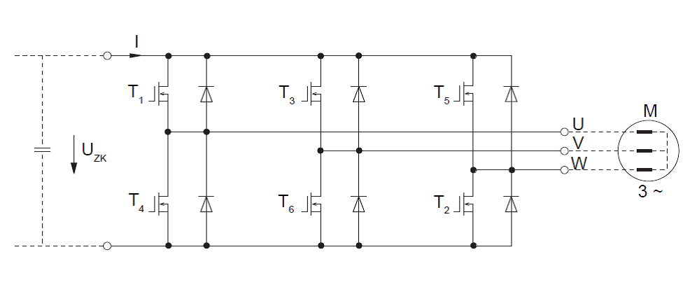
The transistors act as a switch connecting the DC bus across the windings of the motor. A VFD with a 480VAC input will have a DC bus of approximately 678VDC. Thus the ‘pulse’ refers to the switching on and off of the transistors producing a pulse of voltage with an amplitude of approximately 678VDC.
The goal of the PWM control is to create a sine wave current waveform output to produce torque in the motor.
In order for the current to flow between two phases of the motor above, at least one transistor in the top portion of the diagram and one in the bottom of the diagram must be activated. By utilizing specific combinations of transistors, current can be induced in either direction between phases.
For example, if T1 and T6 are open, current will flow from the DC bus positive through the U to V phase of the motor and then to the DC bus negative. If T3 and T4 are open, then the current will flow from the DC bus positive through the V to U phase of the motor to the DC bus negative.
One of the advantages of using a VFD with PWM technology is the ability to control the amount of current going through the motor windings, which when running a rotary industrial motor, translates into controlling the amount of torque at the motor shaft.
In the case of a VFD that utilizes PWM technology, this is done by varying the RMS voltage to the motor. By controlling the amount of time each pulse is on and off, the resulting RMS voltage across the motor phases can be controlled. The ‘width’ of the pulse factors into the resulting RMS voltage output.
A longer ‘ON’ time of the pulse results in a higher RMS voltage across the phases.
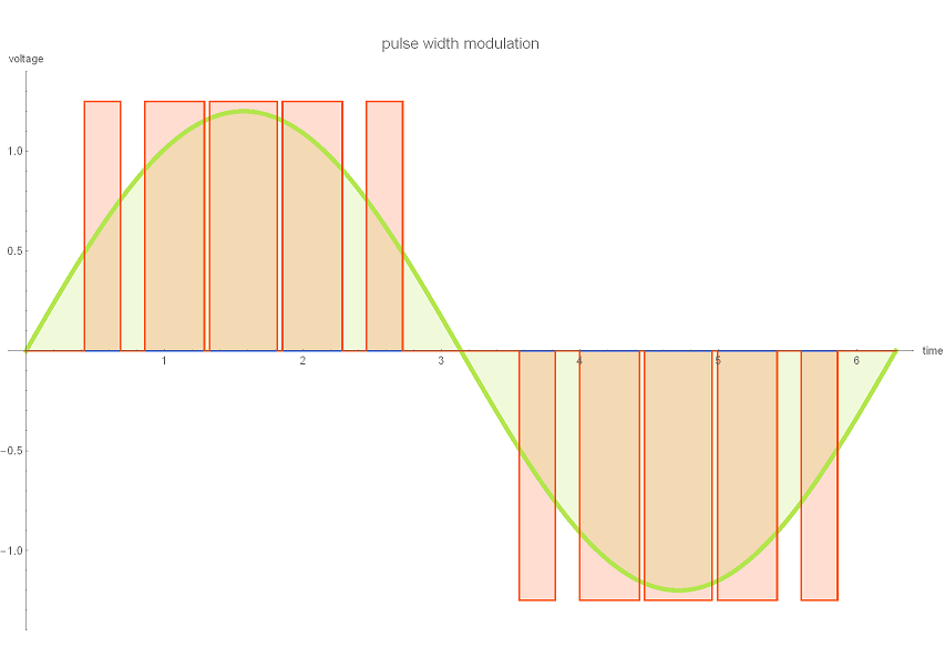
A shorter ‘ON’ time of the pulses results in a lower RMS voltage across the motor phases.
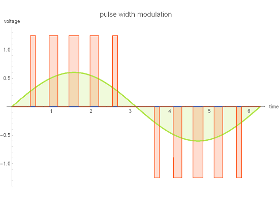
So by modulating the pulse width over each successive half wave, the RMS voltage across the motor phases can be controlled. The resultant variable RMS voltage allows the VFD to vary the amount of current flowing between motor phases. The current waveform produced through the PWM process is also influenced by the IGBT switching frequency.
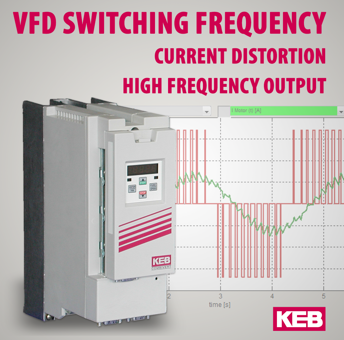
Switching Frequency
The IGBT switching frequency refers to the rate of the on/off switching of the individual IGBTs. Typical switching frequencies used are 4kHz, 8kHz, and even up to 16kHz. A higher switching rate will provide a cleaner waveform to the motor as there will be more pulses over each half-wave.
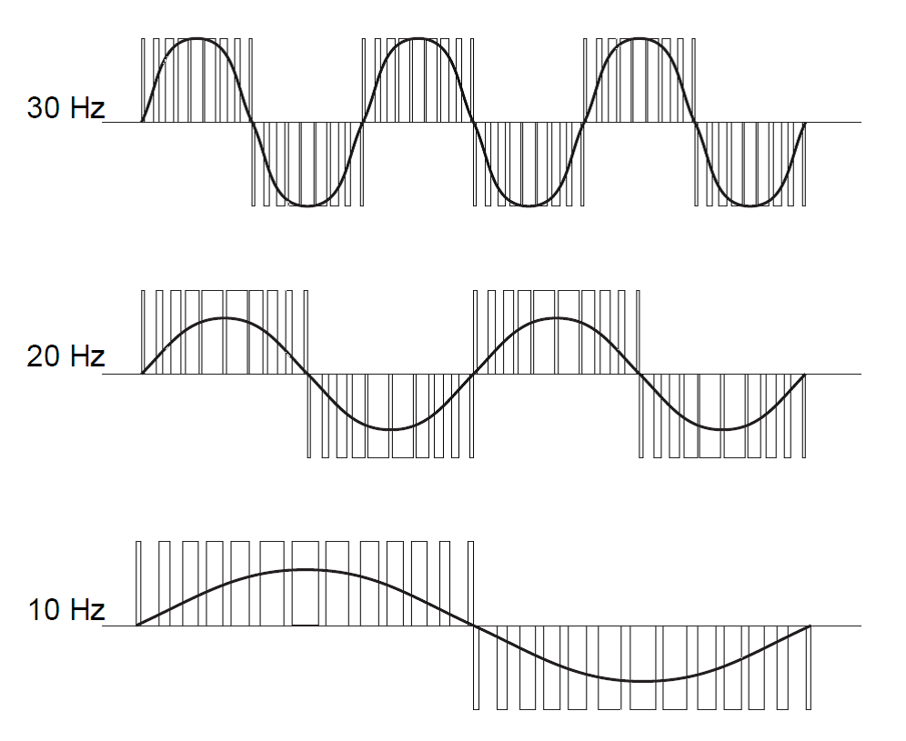
In addition to the motor torque (current), the motor speed (frequency) can also be controlled by utilizing PWM. By changing the period of the voltage pulses which induce the current in the motor phases the resulting output current waveform frequency can be changed.
KEB – The Drive Expert
By coupling the control of the pulse width and the pulse group period, PWM drives provide a means to control both the voltage and frequency output to an AC motor.
The ability to control the torque and speed of an AC motor opens up application possibilities for machine designers. Motor speeds can be optimized for the application to achieve higher system efficiency (i.e. fan control). Motor speeds can be increased above the nominal motor speed to increase production rates. Motor torque can be limited to help protect mechanical components of the system. Controlled starting and stopping of motors can eliminate mechanical components that may wear over time.
Contact a KEB America engineer to discuss how we can apply VFDs to help your application.
Related Articles

Let's Work Together
Connect with us today to learn more about our industrial automation solutions—and how to commission them for your application.