
VFD switching frequency refers to the rate at which the DC bus voltage is switched on and off during the pulse width modulation (PWM) process. The switching on and off of the DC voltage is done by Insulated Gate Bipolar Transistors (IGBTs).
The PWM process utilizes the switching of the IGBTs to create the variable voltage and variable frequency output from the VFD for control of AC induction, permanent magnet synchronous, or DC motors. The switching frequency, sometimes called the “carrier frequency,” is defined using the unit of Hertz (Hz) and is typically in the kHz (Hz*1000) range, typically ranging from 4 to 16khz, or 4000 to 16000 switches on/off per second.
To determine what switching frequency would work best for your application, it is important to look at the advantages and disadvantages as the switching frequency is increased.
Switching Frequency – Effect on Current Distortion
The harmonic content in the current waveform generated by the PWM process is reduced as the switching frequency increases. The ‘cleaner’ waveform results in higher efficiency by reducing the current ripple, which results in lower motor losses. This benefit of a higher switching frequency is more pronounced as the output frequency to the motor increases.
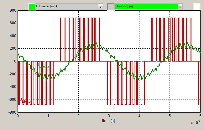
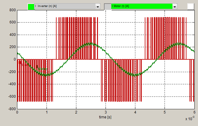
The effects of using different switching frequencies can be seen in the application below. A surface-mount permanent magnet (SMPM) motor is run by a KEB high-speed VFD. The operating point of the system is 50kW @ 10000rpm (333hz). Figure 1 shows the current waveform (green) and the PWM output of the VFD (red) at a 4khz switching frequency. In this application, the required current to reach the operating point is 178amps.
The formula for the total harmonic current distortion (THD(I)) is:
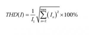
where
I1 = r.m.s. current at the fundamental frequency
In = r.m.s current of nth harmonic
n(max) is the number of the highest measurable or significant harmonic. In this case, the highest harmonic used was n = 50.
For this application, running at 50kW @ 10000rpm, using a 4khz switching frequency, the THD(I) = 12.69%.
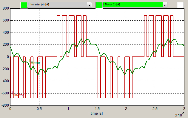
Running the system at the same operation point (50kW at 10000rpm) and increasing the switching frequency to 8khz gives the current waveform at the motor shown in figure 2 and the resulting THD(I) = 6.27%.
The reduced current distortion translates into lower rotor heating of the motor and higher motor efficiency. The reduced rotor heating is of great concern when motors utilize bearing technology that requires very small clearances (airfoil or magnetic). Excess rotor heating can cause the rotor to expand or elongate, which could result in the rotor impacting the bearing surface.
Switching Frequency – Effect on high-frequency outputs
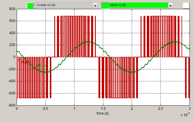
As the motor output frequency increases, the impact of the VFD switching frequency becomes more pronounced. Using the same motor as above, the operating point was increased to 100kW at 20000rpm (666hz). Again, the required output current from the VFD to reach this operation point was 178amps.
At 4khz switching frequency (figure 3), THD(I) = 17.27%.
At 8khz switching frequency (figure 4), THD(I) = 8.47%.
At 16khz switching frequency (figure 5), THD(I) = 4.05%.
The higher switching frequency decreases the audible noise that can be heard from the motor. The audible noise from the motor is a result of the stator laminations vibrating at the carrier frequency rate. As the carrier frequency is increased, the pitch of the noise from the stator laminations is increased moving the levels farther out of the normal hearing range of humans. Motor noise levels may be of concern based on the application requirements (elevator motors, theater equipment, etc.). In these cases, a VFD with a higher carrier frequency may be an option.
As the switching frequency increases, motor heating due to higher harmonic content in the current waveform decreases. At the same time, the heat generated internally in the VFD due to the IGBT switching is increased. Each switching action of the IGBT produces a relatively fixed amount of heat loss. So as switching frequency increases so does the overall heat loss of the VFD. The heatsink of the VFD must be designed to provide sufficient cooling of the VFD to operate during the maximum rated ambient conditions.
KEB drives are rated based on a specific switching frequency. It may be possible for a specific drive to operate at a higher switching frequency than rated, but the output may have to be reduced in order to keep the drive from overheating. If the system requires a higher switching frequency, then the heatsink may need to be increased in size, have increased airflow, or be liquid-cooled. All of these options are available on KEB drives.
Because of the higher heat loss due to the higher switching frequency, and the fact that the heatsink may need to be larger (if air-cooled), this results in a larger physical size VFD and consequently higher initial component costs.
KEB has an option for liquid cooling of the VFD for situations where space may be an issue. While this does potentially reduce the physical size of the VFD housing, it does introduce the requirement for access to a cooling fluid.
The VFD ratings are based on maximum ambient conditions. In most cases, the VFD is mounted inside an electrical enclosure. The maximum ambient temperature around the VFD becomes the temperature inside the enclosure. A higher heat loss from the VFD due to the higher switching frequency introduces more heat loss into the enclosure. The higher enclosure heat load may require additional cooling (fans, air conditioner) to be added to the enclosure itself, depending on the application requirements.
The VFD switching frequency used for a specific application depends heavily on the application requirements and components in the system. Motor design, noise levels, required system efficiency, cooling requirements, and component costs all need to be considered when determining the optimal VFD switching frequency for the application.
Better Machines with Better Drive Technology
KEB VFDs can operate at switching frequencies up to 16khz. KEB has a strong background in applications requiring high switching frequencies. Because of our extensive application experience in these types of applications, KEB drives have been developed to deal with the inherent challenges that come with the higher switching frequencies.
Whether your application requires a high switching frequency or not, KEB America has the options and expertise to help you meet your application requirements. Contact us today or fill out the form below.
Related Articles
Let's Work Together
Connect with us today to learn more about our industrial automation solutions—and how to commission them for your application.