
This post discusses VFD regenerative applications – applications that regenerate energy and the common drive topologies and options that are available.
A motor is simply an energy conversion device. Most commonly, we think of inputting electrical energy to a motor and it converts it to a mechanical torque which does some work on a load. This is called “motoring mode.” But depending on the nature of the connected load, a motor can also operate in the reverse. It can convert torque into electrical energy, this is called “generating mode” or regeneration.
VFD regenerative applications fall under a couple of common categories. First, machines that lift and lower. These include elevators, hoists, cranes, and escalators. Next, applications that control torque like tension unwinders, web handling systems, and test stands. Finally, there are cyclic applications like centrifuges that start and stop large masses.
Basic VFD Topology
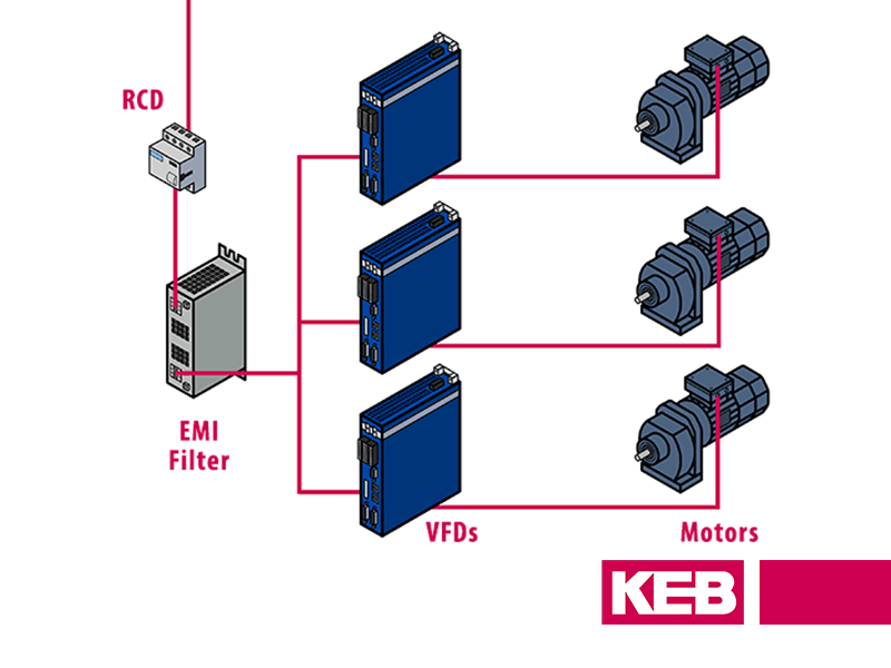
First, some basics – a typical 6-pulse VFD has 3 main parts.
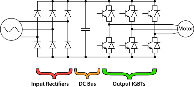
Part 1 is the rectifier stage which converts incoming AC power to DC power. It is important to note that the rectifier stage is like a one-way street and allows energy to flow into the inverter but not back onto the utility. This is important when considering the energy that is regenerated back onto a drive. Without some provision like a brake resistor or regen drive, there is no place for the energy to go.

Part 2 is the DC bus which consists of a capacitor bank that helps smooth out the rectified power and acts as an energy buffer. Part 3 is the transistor or IGBT output stage. The IGBTs use pulse width modulation (PWM) to actively switch on-and-off the DC bus voltage to the motor, resulting in an AC current to the motor. The AC current can potentially flow in both directions across the IGBT so the energy flow here is bi-directional.
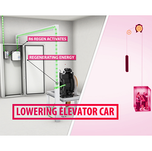
Let’s look at the example of an elevator or hoist. When energy is delivered to the system (“motoring mode”), current flows into the VFD and is output to the motor. The motor provides torque and does some work like lifting a load. As the load is lifted, potential gravitational energy in the system increases and can be explained with the equation:
Gravitational Energy = mass * gravity constant * height of travel
The higher the load is lifted and the larger the mass, the more gravitational energy is in the system.
Eventually, when the load is lowered the motor acts as a generator (“generating mode”), and the potential energy of the system is converted into electrical current which flows back into the VFD. Current is able to flow back across the IGBTs to the bus capacitors but can go no further due to the rectifier stage. The DC bus voltage on the bus capacitors will continue to rise until the drive faults out with an overvoltage error. To avoid this, something needs to be done with the excess energy in the drive.
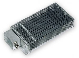
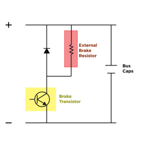
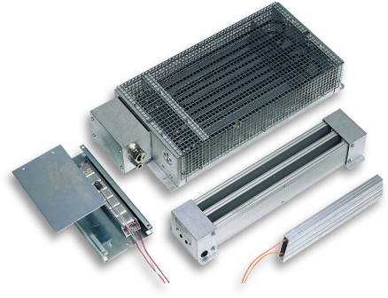
Braking Resistors
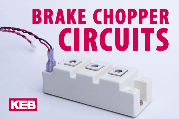
Historically, a brake chopper circuit and a resistor have been used to dissipate excess energy in VFD systems. They function by having a brake transistor circuit, or “chopper”, connected to the VFD’s DC bus capacitor stage. When the DC bus voltage exceeds a certain threshold, the brake transistor circuit closes or is “shunted” and current flows from the capacitors across a large external resistor. The electrical energy in the VFD is converted to heat as the current flows through the resistor. The bigger the load and more regenerated energy you have, the more heat is created.
A few comments about the sizing and design of brake choppers. KEB’s brake circuit is internal to our drives which is very nice and makes for a compact package. Some VFD competitors require a separate chopper circuit which must be placed in the cabinet and requires extra wiring. Additionally, KEB’s chopper circuits are sized on the beefy side. They are rated for 100% of the rated current so they are great for applications where substantial regen is present and for long duties. Other VFD competitors often place a duty cycle (e.g. 50%) on their chopper circuit. In some crane applications I have worked on, users must upsize the entire drive because a larger brake circuit is needed. Always consider the ratings and duty of this circuit.
Common DC Bus Topology
For multi-axis applications like an automated storage retrieval (ASR) crane, one good option is to use a shared DC bus topology. In this scenario, the DC bus capacitors from multiple drives are connected together. This allows the power to flow freely between the drives.
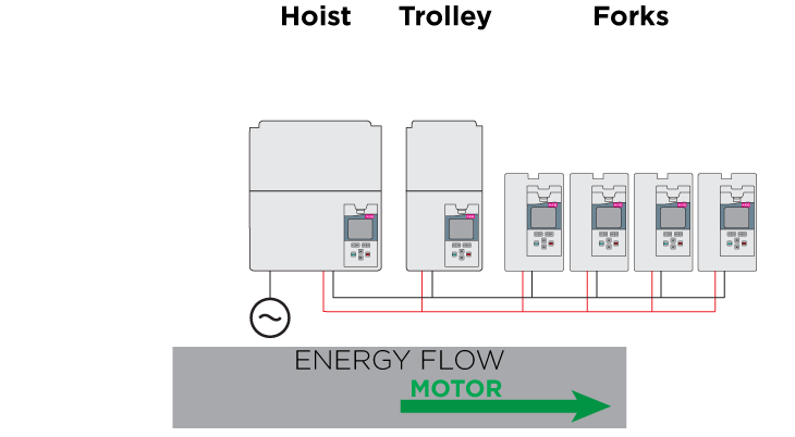
In the case where one axis is regenerating (e.g. hoist axis), the excess energy is shared with the other drives. If a second axis (e.g. trolley) is in motoring mode, it will use the hoist’s regenerated energy. If the regenerated energy is not consumed by other connected loads, then a braking resistor is still required. Typically, it is possible to get by with only 1 resistor rather than an individual resistor for each drive and the net result is less energy consumption.
KEB drives have a DC bus connection which allows the drives to be easily coupled together. One point to make is that the drives do not contain DC fusing so an external fuse would likely need to be used.
Another consideration for shared DC bus topologies is in regards to the input power rectification. Individually connecting each drive to AC power and connecting their DC buses might cause the units to charge unevenly or to get circle currents. This could very easily damage the input stage of the drive and cause failure. So, it is recommended that the system is charged through a single unit that is properly dimensioned or to use diodes to restrict current flow as needed. This could be done through a dedicated bridge rectifier unit. Alternatively, the largest drive with the largest rectifier stage might be able to hand the system’s input power. The ability to do this depends on the specific application and sizing.
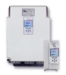
Line Regenerative Drive – KEB R6
Instead of using a braking resistor, it is possible to use KEB’s R6 Line Regenerative drive. The R6 also has DC bus capacitors and is DC bus coupled to the other VFDs. The R6 uses advanced software to continuously measure and match the utility line voltage and frequency. When the DC bus voltage on the system is above a certain threshold the R6 unit activates and it switches its IGBTs on/off to commutate current back to the line. When the DC bus voltage falls back below the threshold, the R6 unit goes into standby mode.
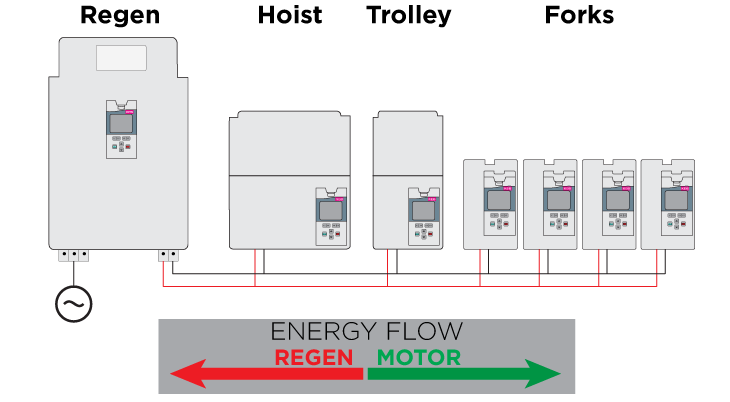
Another way to think of the R6 operation is that it enables two-way energy flow in a VFD system. The regenerated energy can flow back onto the line where it is typically consumed by other electrical loads in the building or factory.

The KEB R6 also has the ability to act as the system rectifier. If dimensioned properly, the R6 can rectify all incoming power and can be DC-bus connected to the inverters. Again, this topology simplifies the charging sequence upon start-up as all input current flows through the R6.
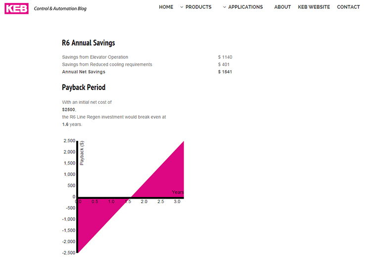
Besides the net energy savings, another advantage to using an R6 regen unit instead of a braking resistor is that less heat is created. As mentioned, braking resistors can create a lot of heat. In some applications, this heat needs to be removed from the machine room or control cabinet which requires an additional A/C unit. An A/C unit in turn requires energy to operate. Applications like a cold-storage storage retrieval crane clearly favor regen technology and can show ROI of fewer than 18 months considering 24/7 crane operation.
H6 – Multi-Axis Drive
KEB’s H6 multi-axis drive combines both a shared bus and the ability to regenerate back to the line in a tightly integrated solution. The H6 has separate modules which easily connect to each other. H6 Modules include a rectifier, active front end (allows line regen), 24VDC supply, IEC61131-3 PLC control, and single and dual output drive modules. The modules have a DC bus rail which allows for an easy connection for power-sharing.
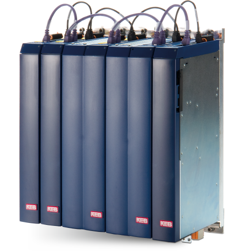
An active front end or AFE module also exists which allows for line regeneration if needed. The AFE can be coupled together with an LCL filter which provides extremely low harmonic performance.
A big advantage of the H6 is that it has been designed from the ground up as a multi-axis drive. Items like module fusing, DC bus connections, and synchronizing the control of the units are all engineered to ease set-up and provide excellent performance. Another advantage is the drive footprint. For example, a drive solution for a 55kW storage retrieval crane consisting of a hoist, trolley, and 4 forks can be achieved with an H6 in about 60% of the space – allowing for a smaller control cabinet to be used.
Better Machines with Regen Drives
An engineer has choices when it comes to dealing with regenerative energy in VFD applications. Each solution has its advantages and disadvantages.
If you’d like to learn more about KEB control and automation solutions, you can reach a KEB America engineer using the form below.
Related Articles
Let's Work Together
Connect with us today to learn more about our industrial automation solutions—and how to commission them for your application.