

Across KEB’s line of inverters, a PI controller is used whenever closed-loop control is utilized. This blog post and the accompanying YouTube video describe how this PI controller is used in a VFD to provide precise speed and torque control of the motor.
What is the PI Algorithm?
The PI (Proportional and Integral) controller is a commonly used method in control systems to correct for error between the commanded setpoint and the actual value based on some type of feedback.
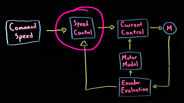
In the case of KEB drives, the PI controller is implemented in the speed control portion of the closed-loop control block diagram. The command speed could be from a PLC, while the provided feedback can be from an encoder or calculated based on our Sensorless Closed Loop (SCL) control.
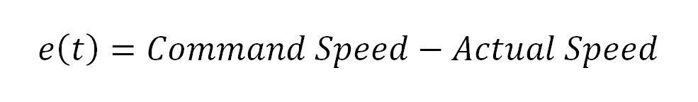
The first step of the PI controller is simply to calculate the margin of error between the commanded and actual speed at that specific point of time. This error is then fed into the PI control algorithm, which can be broken into its respective Proportional and Integral parts.
Proportional Control
The first step of the PI controller in a VFD is the proportional control, which is the simpler of the two. The proportional control is used to immediately respond to any error between the command and actual speeds. The larger the error, the more effect the proportional controller will have on the output in order to eliminate the error as quickly as possible.
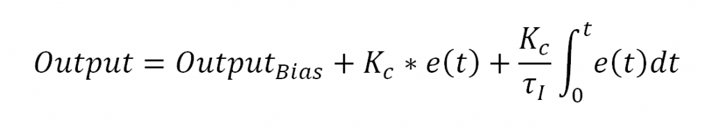
The first term in this section is the Bias. This is a constant value and is typically set equal to the initial commanded output. Thus with no initial error, there would be a smooth transition from open to closed loop.
Added to this bias are the product of the error at that point in time and the proportional controller gain. This gain is a programmable value in the KEB drive. The higher the value, the quicker the control will adapt to error. However, if the gain is too high, it will overshoot the command because it is over-controlling.
Integral Control
The second step of the PI controller is the integral control, which adds a little bit more complexity to the control. The integral control is used to eliminate long-term error and offset in the system.
Integral control still uses the proportional controller gain but adds the integral controller time constant, which is also programmable in the drive. These two parameters influence each other, so it may take some trial and error in tuning the control to get them at their ideal values when first starting up a system.
Importantly, the integral control considers the complete integral sum of the error rather than the current size of the error. Thus, the integral control will still be affecting the output if there is a built-up long-term error, even if there is no error at that specific point in time. The other thing to note about the integral term is that it is dividing by the integral time constant. Because of this, a smaller value will have more effect on the control.
PI Controller Implementation
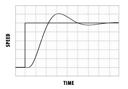
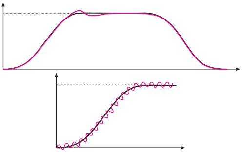
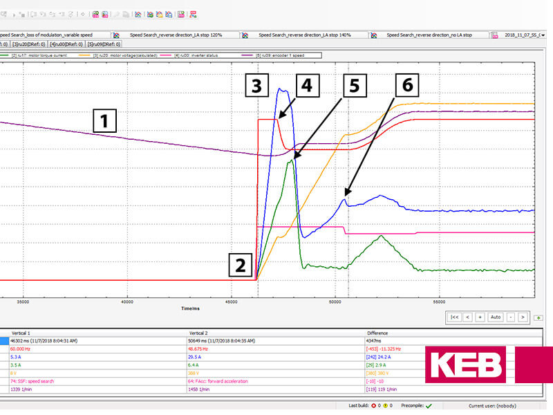
In the graph above, you can see the command speed jump straight from zero to the set point. However, due to real-world factors such as load inertia or current limits, the actual speed can’t perfectly follow this command. Thus, the PI Controller in a VFD is implemented to make the actual speed follow the command as closely as possible.
Proportional Control Implementation
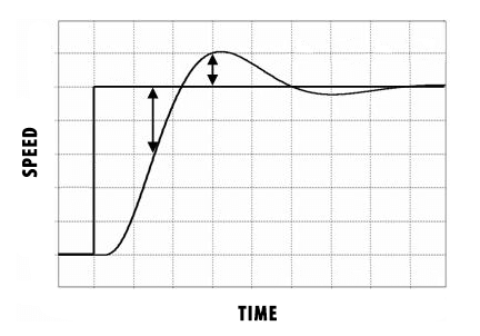
To implement the proportional controller, you would first simply calculate the error at each point in time by subtracting the actual speed from the command speed. This value would then be multiplied by the proportional control gain and then added to the bias. Thus a large error with a large proportional control gain would have a large effect on the output command, while a small error with a small gain would have a minimal effect.
Integral Control Implementation
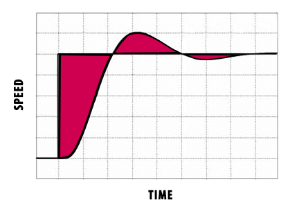
The integral control portion is more difficult to calculate because rather than simply subtracting the actual speed from the command speed, you must calculate the integral of the error from time zero to the current time. A rough estimate can be calculated by adding up all of the boxes between the command and actual value curves. This total sum of error is then multiplied by the proportional gain and divided by the integral time constant. This value is then added to the proportional term of the control algorithm to achieve the true PI controller output.
PI Controller Benefits
The PI Controller in a VFD is a relatively simple way to achieve a robust and fast responding closed-loop control system. By adjusting two parameters, the drive can quickly respond to errors between the command and actual speed while also eliminating any long-term error in the system. This allows the KEB drive to achieve precise speed control of the motor.
Interested in how the PI controller used for closed-loop control in KEB drives could benefit your machine? Contact an Applications Engineer at KEB America today.
Related Articles
Let's Work Together
Connect with us today to learn more about our industrial automation solutions—and how to commission them for your application.