
Braking circuits are essential to the proper operation of systems that employ a variable frequency drive (VFD) and electric motor controlling a high inertia load. Cranes, elevators, and centrifuges are just a few applications in which the VFD will be subject to potentially large amounts of regenerated energy from the motor.
The CEMF (counter electromotive force) created by a running motor increases during deceleration or overhauling, essentially turning the motor into an electric generator. The rate of deceleration/overhauling and size of the load will determine how much CEMF voltage is generated. This voltage will add to the voltage already present on the drive’s DC bus capacitors.
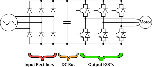
In general, VFDs are not designed to return energy from a motor back to the utility. The input bridge rectifiers of the drive will only allow for supply power in and cannot pass power back to the main supply.
Related Video: How Pulse Width Modulation Works in a VFD
Consequently, the DC bus voltage will increase with the voltage received back from the motor. If the voltage level rises above the maximum rating of the capacitors, then damage will result.
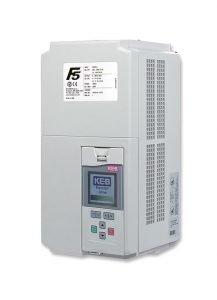
So, an intermediate braking circuit is necessary to dissipate the excess voltage. Let’s take a look at how this is accomplished with the KEB F5 inverter.
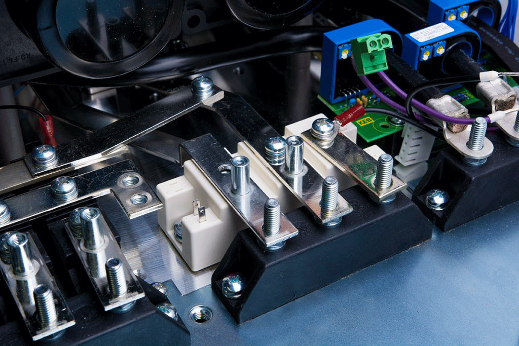
Brake chopper
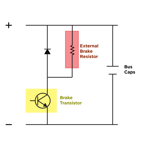
Typically, a braking circuit (sometimes known as the “chopper” circuit) is controlled by the drive and consists of a power transistor and resistor(s) that are connected across the drive’s DC bus.
F5 drives come in both 200V and 400V models. Working with a 400V model F5 on a 3-phase supply voltage of 480VAC, the drive will measure an idle bus voltage of 672VDC (480VAC x √3). The default voltage level at which the F5 will trigger the braking transistor is 780VDC (380VDC for 200V models) – this level is programmable.
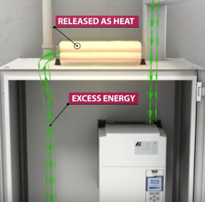
The F5 will monitor the bus voltage and if it begins to rise above the trigger level, it will turn on the braking transistor, sending current flow to the braking resistor(s) where the energy will be used up in the form of heat.
Once the bus voltage falls below the trigger level, the F5 will turn off the braking transistor. The F5’s maximum DC bus voltage level is 840VDC (420VDC for 200V models). If for some reason there is a failure in the braking circuit (i.e. open braking resistor) and the excess voltage can’t be dispersed, the F5 will trigger the error E.OP (over-potential) when the DC bus voltage reaches higher than the rated maximum value. When the error is triggered, the drive will stop operation.
Integrated brake transistor
The KEB F5 Combivert excels in applications that demand muscular and reliable braking. It has a strong, integral braking transistor rated for a 100% duty cycle. Some VFD manufacturers do not incorporate the braking transistor in their drives and instead, offer a separate braking module. This means more space is required to accommodate extra hardware at added cost.
Moreover, the braking transistor duty rating of other manufacturers’ drives is often less than 100%, which means that the drive or braking module may need to be oversized in order to handle the braking current.
Given these considerations, it is easy to see why the F5 is the VFD of choice for many OEMs.
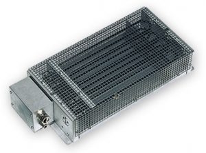
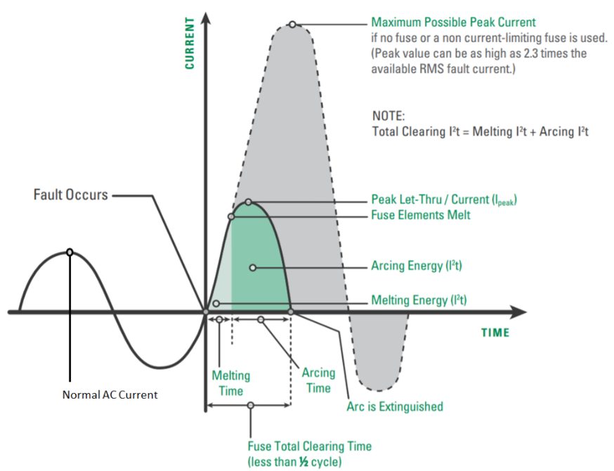
When implementing a braking circuit, the size and specifications of the braking resistor(s) must also be taken into account. They must be sized correctly or damage can occur. If the resistance is too low, the braking transistor’s rated maximum braking current could be exceeded, causing damage to the braking circuit.
If the resistance is too high, then the excess voltage will not be sufficiently dissipated, resulting in over-voltage. Over time, repeated exposure to over-voltage can cause damage to the DC bus capacitors, resulting in drive failure. For assistance with proper resistor sizing, KEB provides the minimum and typical resistance ratings along with other braking circuit data in the front of the drive manual.
Regenerative drives
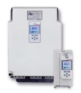
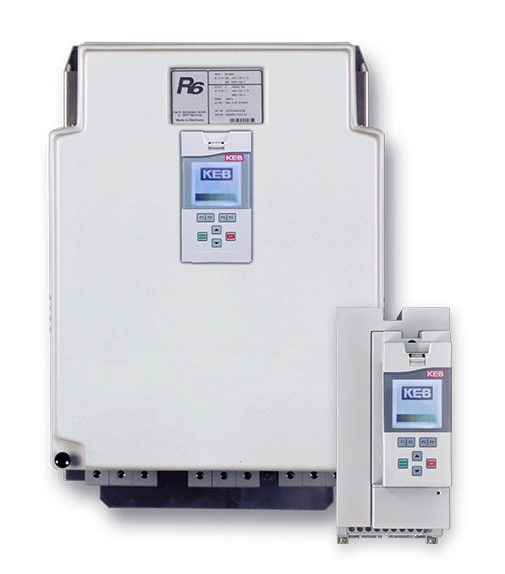
As an alternative to the traditional braking circuit, KEB offers the R6 regenerative unit. This unit acts as the power supply for the VFD and transfers regenerative energy from the motor back to the line. The returned energy can be used by other electrical loads in the building and since there is no heat being generated by a braking resistor, less energy is used for cooling the machine room. This can mean significant energy cost savings.
The R6 is coupled to the DC bus of the VFD and like the VFD, it constantly monitors the DC bus voltage. The R6 detects the supply voltage level and will automatically configure itself for 200VAC or 400VAC operation. When the bus voltage starts to go above 103% of the nominal DC bus voltage, the R6 will change from standby to regen mode; returning the regenerative energy to the mainline (480VAC supply = 672VDC bus; the R6 would regenerate around 692VDC).
Auxiliary braking resistors may still be needed when the R6 unit cannot operate in regen mode. (i.e. building running off of UPS supply or battery backup). The F5 triggers its braking transistor at a higher voltage level than the regenerative voltage level of the R6, giving the braking system some redundancy when needed.
Whatever the application, the KEB F5 and R6 provide the perfect braking solution.
Related Articles
Let's Work Together
Connect with us today to learn more about our industrial automation solutions—and how to commission them for your application.