
T6 Auxiliary Inverter Setup for eMobility Applications
The T6 Auxiliary Inverter setup for eMobility applications is quick and easy. This demonstration walks through the setup process from start to finish. Let’s begin with the default settings to set up a permanent magnet servo motor to run in sensorless operation with CAN J1939 process data commands.
For a video tutorial, you can watch the one below hosted on our YouTube channel.
Open COMBIVIS Software for T6 Auxiliary Inverter Setup
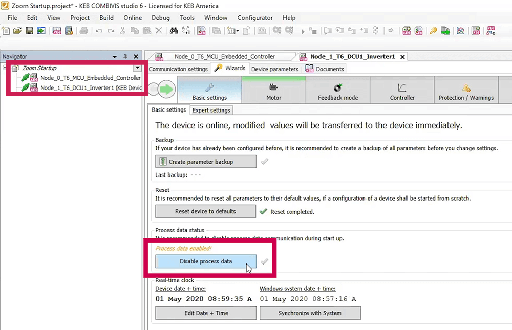
First, I will launch Combivis, the free software for KEB inverter setup and troubleshooting. As you can see in Figure 1, there are two nodes, one for the embedded controller (MCU) and one for the inverter control (DCU).
Open the Wizards Dashboard
I’ll start with the inverter. When you select the inverter node on the left, it opens the Wizards dashboard. I’ll step through the wizards needed to setup up the inverter to run the motor. Starting in the basic settings tab, I disable the process data since I do not have the CAN bus set up.
Enter Motor Nameplate Data
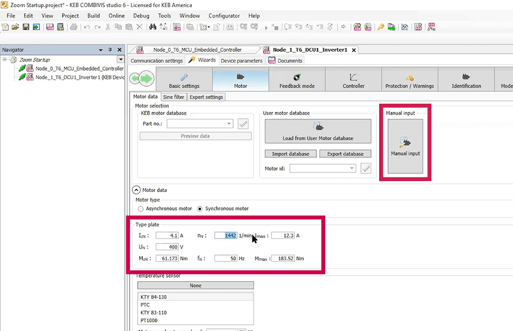
Then, in the MOTOR DATA tab, I will select the manual input button, the correct motor type, and enter the basic motor nameplate data. This includes the motor rated current, speed, voltage, torque, and frequency.
Inverter Feedback
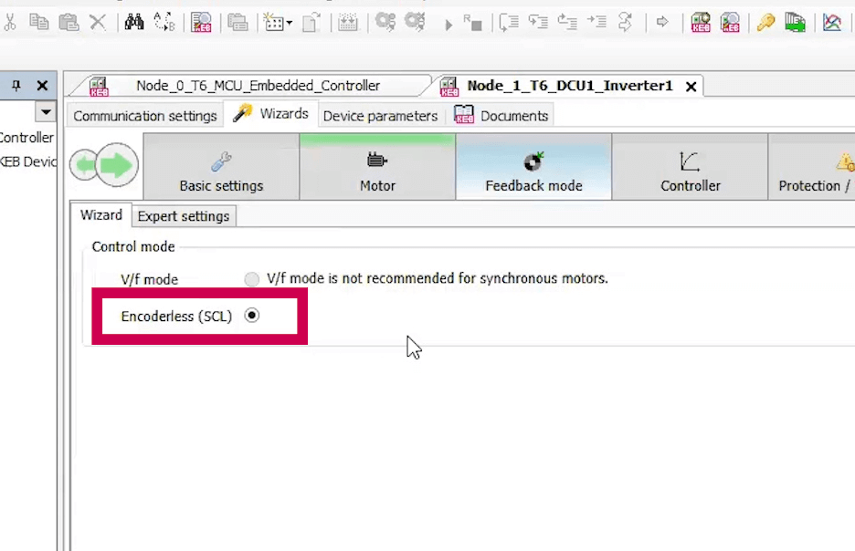
Then, in the FEEDBACK tab, I’ll ensure that Encoderless control is selected. This is KEB’s proprietary Sensorless Closed Loop (SCL) motor control that offers precise control without the need of an encoder.
Inertia Value – Controller Tab
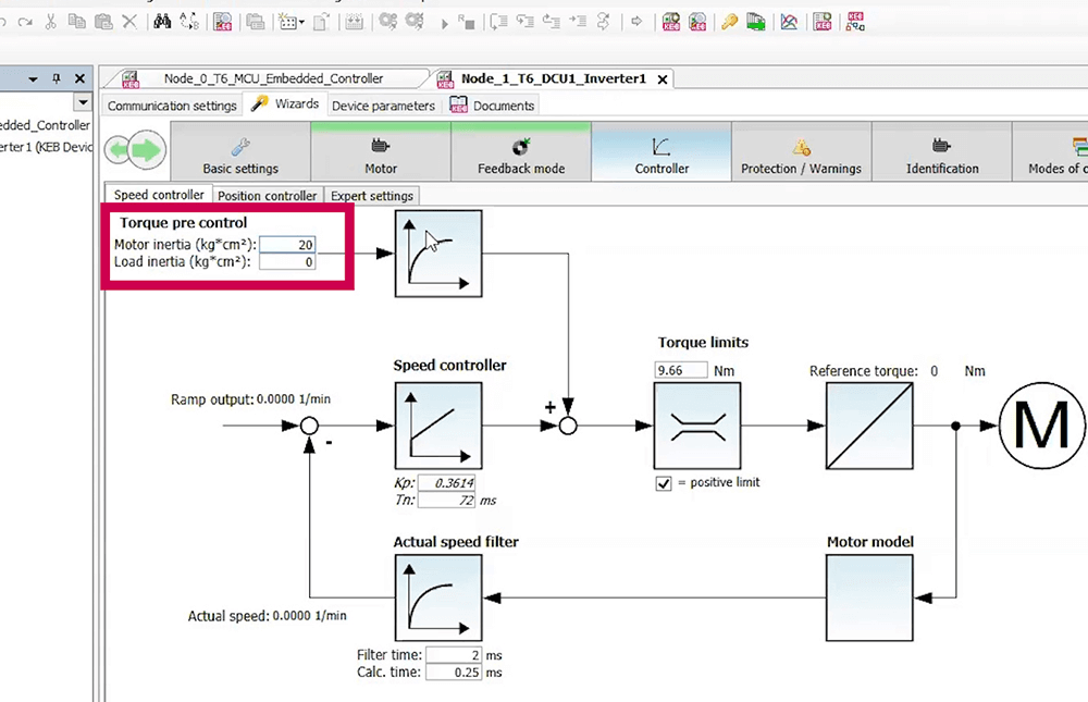
Then in the CONTROLLER data tab, I’ll put in a nominal for the inertia value; this pre-calibrates the speed control PI-loop.
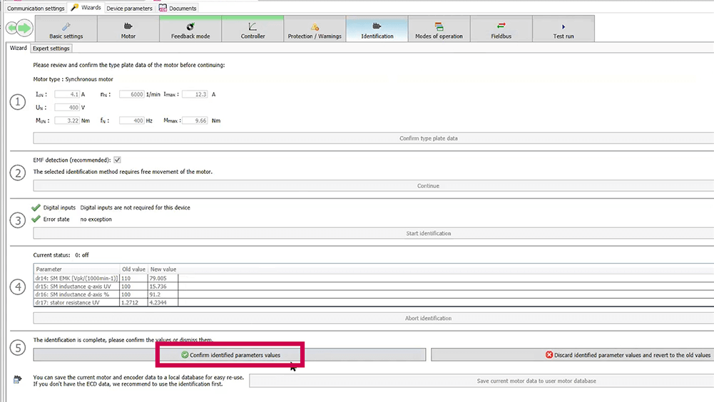
Motor Learn Process
Then, in the (MOTOR) IDENTIFICATION tab, I’ll go through the steps to start the motor learn process. Then, give the hardware enable to initiate the motor data learn. You will hear the process start and will typically take 2 – 3 minutes.
During the process, the inverter will learn the motor resistances and inductances then towards the end will ramp up to speed to measure other characteristics. When the process is complete, I’ll click to confirm and save the data. And, turn off the hardware enable.
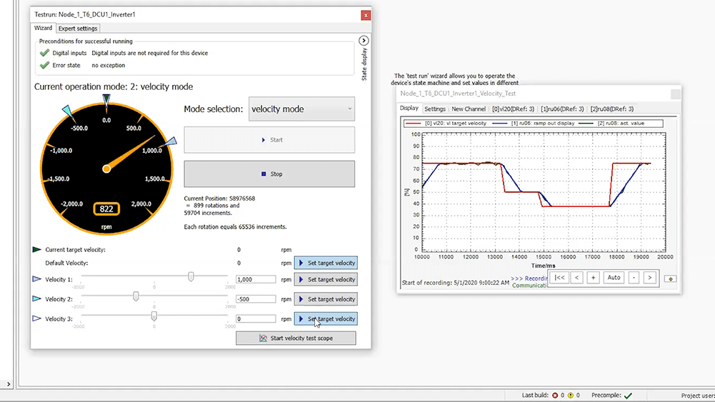
Test Run the Inverter and Motor Function
Next, I can go to the Test Run tab and start the test wizard. Enter in some values for speeds (so, 1,000 rpm, -500 rpm). I can also select a pre-configured scope trace which shows the command speed and actual speed. Then, I’ll give it the start command and a hardware enable.
I’ll select the different speeds and watch the scope to make sure it’s ramping up to speed. I will test going back down to zero then the other direction to make sure everything is functioning properly and sending the correct feedback to the COMBIVIS software.
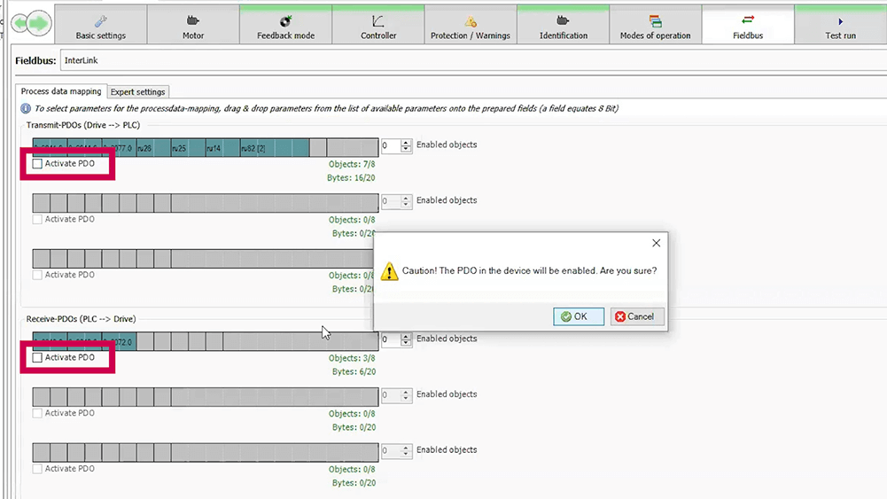
Activate CAN Process Data in the Fieldbus Tab
Now that the motor is running I can activate the CAN process data. Go to the Fieldbus tab and then activate the process data mappings.
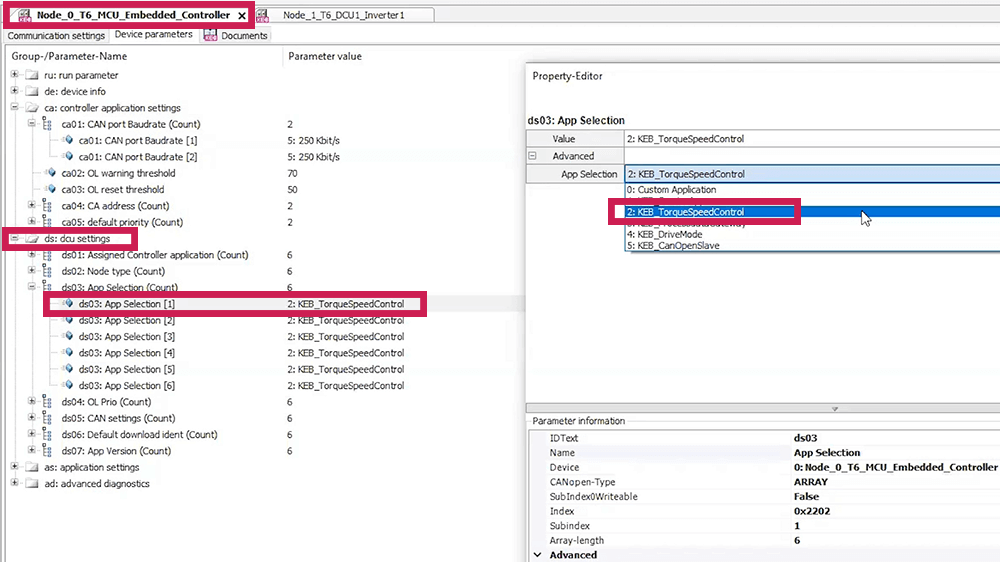
Embedded Controller Tab
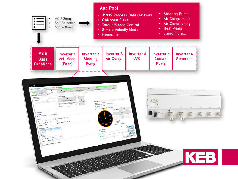
Now, I can switch over to the embedded controller node tab near the top of the program window. I will enter controller settings, like the CAN baud rate. Next, I’ll select the application to run for the inverter node. Applications are preconfigured programs and there are different options available. I will use the default torque and speed control app called 2: KEB_TorqueSpeedControl. This will preconfigure the CAN process data mappings.
Then there are the corresponding application settings. We don’t have a wizard for this yet. But, some of the typical parameters would be things like CAN cycle times.
Third Party CAN Controller Software
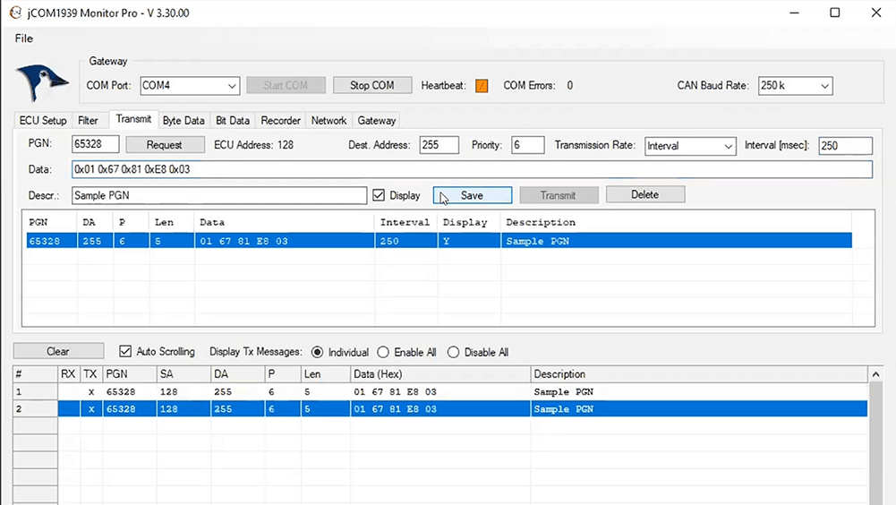
This is my third-party CAN controller program. In the top Gateway section of the program, select Start comm. I will go to the ECU Setup tab to select ECU simulation mode and claim an ECU address by selecting Claim Address.
Then, I will go to the Transmit tab and enter the PGN number of the DCU node I want to write to. I will set up cyclic data, then paste in the data I want to send and send that through the bus. You will then see communication begin to populate below. What I’m sending is essentially a start command and a speed command.
COMBIVIS Confirm Device Feedback
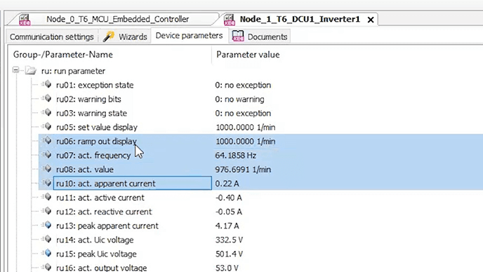
I can now go back to my Combivis program, look in the Device parameter (DCU), and open up the “ru” parameter group. You will see a speed command, a feedback command, and the current and voltage output.
Conclusion
Now you know how to perform a KEB T6 Auxiliary Inverter startup, running a permanent magnet servo motor in sensorless operation with CAN J1939 process data. If you have questions about the T6 or any other KEB product, please use the contact form below.
Related Articles

Let's Work Together
Connect with us today to learn more about our industrial automation solutions—and how to commission them for your application.