
How to Choose the Best VFD Cooling Method for Your Industrial Machine
Variable frequency drives (VFD) are integral to many industrial automation systems. Efficiently dissipating the heat generated by the VFD during normal operation allows the VFD to function properly and provide the best usable lifetime of the system. The type of VFD cooling used depends on the application requirements, expected ambient conditions, and available cooling medium.
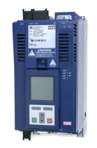
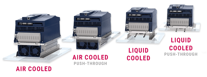
KEB F6 VFDs are available with multiple cooling options to best suit the application. Air-cooled units are available in traditional panel-mount versions as well as through mount options. Liquid-cooled units are available in panel mount and through mount configurations.
Air Cooling
Air cooling for VFDs is the most used option. Air cooling provides a simple, reliable cooling method without requiring any external cooling medium. The KEB F6 air-cooled unit utilizes a finned heatsink with cooling fans to force air across the fins. The heatsink is housed in a sheet metal frame to force the air over the cooling fins for maximum heat transfer.
Standard Air Cooling Configuration
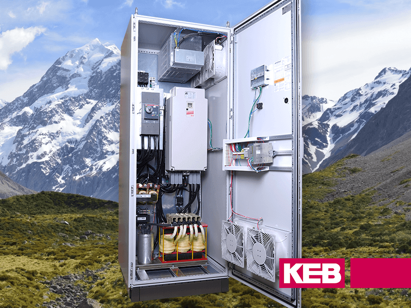
The standard air-cooled F6 VFD is designed to be mounted in an electrical enclosure. The heatsink frame incorporates mounting feet for easy mounting of the unit on the back panel of the electrical enclosure. Power for the fans is provided by the 24vdc supply used to power the VFD control system. The heatsink cooling fans of the KEB F6 system activate based on the actual heatsink temperature measured by an onboard temperature sensor. This allows the fans to run only when required based on the actual temperature of the VFD.
Since the VFD is mounted inside the electrical enclosure, once the heat is dissipated, it is deposited inside the enclosure. Care must be taken to provide adequate ventilation and/or cooling of the electrical enclosure to keep the internal ambient temperature below the maximum operating temperature of the VFD.
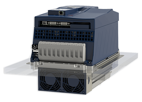
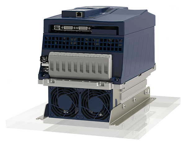
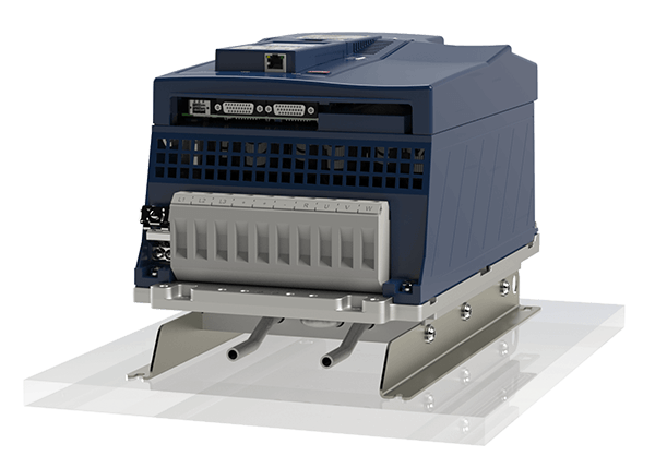
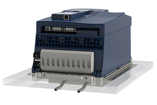
Push-through Air Cooling Configuration
A variant of the standard panel mount air-cooled VFD option is a push-through or through mount heatsink option. This version replaces the mounting feet of the heatsink housing with a flange to allow the finned portion, along with the cooling fans, to be mounted outside the electrical enclosure. This option requires a precise cutout in the enclosure as the heatsink and power stage of the VFD are still one complete assembly. KEB also offers an optional gasket to seal the enclosure from penetration from dust or moisture.
When using the properly mounted push-through option, approximately 70% of the heat created by the VFD during normal operation is dissipated outside the electrical enclosure. By reducing the amount of heat dissipated from the VFD inside the enclosure, the overall cooling requirement of the enclosure system is reduced. By reducing the amount of heat dissipated inside the enclosure, the enclosure size may be reduced as well.
With the heatsink cooling fans located outside the enclosure, the environment where the system is installed must be considered when evaluating whether this type of cooling is best for the application. Through-mount heatsink designs are typically used on systems installed indoors in conditioned spaces, as the heatsink fans are not rated for outdoor use.
A few additional application considerations when using air-cooled VFDs include the application’s altitude, expected loading, VFD switching frequency, and expected ambient conditions.
The KEB F6 VFD heatsinks are designed to dissipate the heat generated when the unit runs at full-rated power and current at a defined switching frequency (4khz for example). If a higher switching frequency is needed (See switching frequency blog), this increases the heat generated by the drive. In this case, depending on the VFD load, the heat dissipated by the air-cooled heatsink may not be sufficient to keep the VFD within normal operating conditions. A larger housing may be needed to increase the surface area of the heatsink to increase the heat dissipation capacity.
Considerations for High-Altitude Applications
As the altitude increases, the cooling capacity of the air itself is reduced. At altitudes above 1000m, to avoid an overheating condition of the VFD, the rated point of the VFD should be reduced by 1% for every 100m above 1000m. The derating is done to account for the decreased thermal capacity of the air.
Read More: Mastering the Challenges of Using VFDs at high-altitudes VFD Considerations
If the application will be installed in an area that is expected to have very high ambient conditions (for example ambient conditions expected above 55C), the high air temperature will also reduce the amount of heat that the air can remove from the VFD. Options in this case may involve more aggressive enclosure cooling methods like air conditioning or using an oversized VFD housing to allow for a larger heatsink.
Liquid Cooling for VFDs
Liquid cooling for the VFD is another option offered by KEB. Liquid cooling provides higher power density compared to air cooling due to its enhanced heat dissipation capacity. Liquid cooling also does not have the same altitude restriction as air-cooling so derating the VFD at higher altitudes is not needed.
The liquid-cooled option also provides a solution for demanding applications that may have high ambient conditions or require high switching frequency from the VFD.
Learn how a blown film extrusion machines user saves nearly $30,000 on annual electricity expenses by retrofitting machines with KEB’s F6 liquid cooling VFDs.
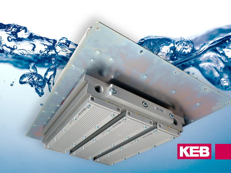
Two Types of Liquid Cooling
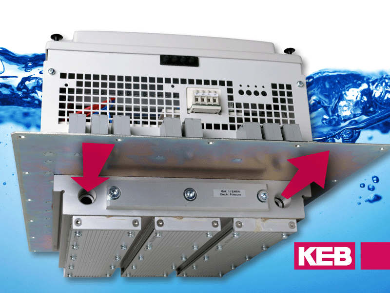
The KEB F6 VFD has two different liquid cooling configurations. Like the air-cooled units, the liquid-cooled units can be panel mounted or utilize a push-through style heatsink. The push-through style heatsink again requires a cutout in the enclosure and has an available gasket to seal the system from contamination. The configuration of the push-through heatsink moves the liquid cooling connections outside the enclosure, separating the liquid cooling connections from the high-voltage main power connections of the VFD, inside the enclosure.
With more than 25 years of manufacturing liquid-cooled VFD systems, in addition to the mounting configuration options above, KEB has developed unique options to enhance the benefits of the liquid-cooled system.
Benefits of Liquid VFD Cooling
Stainless cooling channels: The F6 liquid-cooled option utilizes stainless cooling tubes embedded into an aluminum heatsink. The stainless cooling tubes allow the F6 to utilize water or water/glycol as a cooling medium and refrigerant. The stainless cooling tubes do not have any seals or O-rings, so material compatibility with the cooling medium is not a concern.
Open coolant pipe ends: The KEB F6 comes standard with open pipe ends for connection of the cooling system. This allows the machine builder to choose the type of fittings that work best for their application and gives more available options for coolant connections.
Coolant control algorithm: The KEB F6 includes a flow control algorithm to minimize potential condensation in high-humidity applications. The flow control is set up based on a programmable heatsink temperature. Utilizing the actual heatsink temperature of the F6, the KEB F6 can control an external valve to maintain the heatsink temperature at the programmed level. In applications that subject the VFD to high-humidity air, the programmed level can be set to a temperature above the dew point. In addition, in applications where the cooling medium inlet temperature may vary, the flow control can help reduce the required coolant flow when coolant is at a lower temperature.
High operating pressure: The KEB F6 liquid cooling has a max operating pressure of 10bar (147 psi). The high operation pressure allows for more flexibility based on available cooling options. For example, cooling towers located on high rooftops or refrigerant can be used at higher operating pressures, possibly eliminating the need for pressure-reducing valves.
Reduced physical size: Liquid cooling is much more efficient than air cooling. In many cases, you can reduce the physical size of a VFD when using the liquid cooling option as compared to an air-cooled VFD of the same power rating. This can be very beneficial when space is limited or weight is an issue for the application.
No de-rating at high altitudes: As the operating altitude of a VFD increases, the cooling capacity of air decreases. Thus an air-cooled VFD must be de-rated to avoid overheating. The cooling capacity of the liquid cooling medium is not reduced with altitude. This may allow the VFD to be utilized to the full rated capacity or reduce the unit’s physical size in high-altitude applications.
High frequency, high power operation: High frequency (>600 Hz) applications typically utilize higher switching frequency of the output transistors (≥6khz). Higher switching frequencies mean more heat developed in the drive. As the required output power increases, air cooling becomes more limited in its effectiveness to keep the VFD within the rated operating temperature. The increased cooling efficiency of the KEB F6 VFD liquid cooling option increases the available power range for high-frequency applications.
Increased component lifetime: The operating temperature of air-cooled VFDs fluctuate based on the ambient temperature of the air. In applications that may have large swings in ambient conditions, the fluctuation of the operating temperature of the VFD can put additional stress on the components. By utilizing a liquid cooling medium that stays at a more stable temperature as the ambient conditions fluctuate, the operating temperature of the VFD stays more stable increasing the lifetime of the components.
Liquid Cooling and Air Cooling VFDs from KEB
Various thermal management systems are available for VFD cooling and KEB’s decades of experience can help guide you to the best solution. Both liquid and air-cooling offer different advantages and disadvantages depending on the design and environment of your application. Most systems enjoy the relative simplicity and economical benefits of air-cooled VFDs. However, if you need higher performance or operate in an enclosed system, liquid cooling could be your solution. KEB offers a variety of configurations that suit your needs, and if you have questions, contact an application engineer to find the best cooling method for your application.
Related Articles

Let's Work Together
Connect with us today to learn more about our industrial automation solutions—and how to commission them for your application.