
Mastering the Challenges of using VFDs at High Altitudes
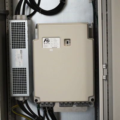
“My electrical enclosure and VFD will be installed at a high elevation – what precautions do I need to take?” This is a question that customers ask from time to time. Any VFD-operated equipment such as pumps, HVAC fans, chairlifts, and satellites that is installed in mountainous areas is affected by this.
There are two main challenges when operating VFDs at high altitudes – reduced cooling capacity and creepage and clearance distances. This post discusses the main considerations and options when using drives at high altitudes.
Challenge 1 – Thinner air and reduced cooling capability
Being from Minnesota, I have jokingly been called a “lowlander” by friends that live in Colorado. My body reminds me of it when I go to the mountains and do any strenuous activity like hiking or skiing. I feel the effects of the “thin air”. At high altitudes, there is less air pressure and fewer molecules in a given volume of air.
The lower air pressure has implications when it comes to cooling electronics. During normal operation, the drive’s IGBTs will create heat as they turn on and off. Most commercial VFDs use a fan to force air across a finned heatsink where the IGBTs are seated. With less air pressure (molecules/volume of air) the cooling capacity of the surrounding air is decreased.
Optimize the Drive Operation
An engineer has several options to combat this. First, they can optimize the drive operation in a way that reduces IGBT heating. This could mean lowering the switching frequency of the IGBTs. Or, possibly operating the motor intermittently or reducing peak loading.
Derate the Drive
The altitude derate for drives typically takes the form of reduced amps output. Check with your specific VFD manufacturer, but most drives have a derate that looks similar to this:
The second common option is to derate the drive. In other words, operate the drive below its normal ratings. Adjusting operating parameters and derating the drive are the most commonly used options because they require no additional components or investments.
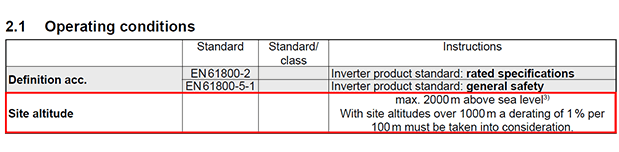
All listed drive ratings such as rated current and peak current are applicable up to a certain elevation like 1000m. Above 1000m, there is a linear derate applied, in this case 1% per 100m. Often times there is a “maximum altitude” listed that should not be exceeded (See Challenge 2 below).
Add Air Conditioning
Another option to offset the reduced cooling capacity would be to add an air conditioning unit in the enclosure that has the ability to sufficiently regulate the enclosure cabinet at the specified altitude. This adds cost to the system but could be more cost-effective instead of upsizing the drive to the next frame size.
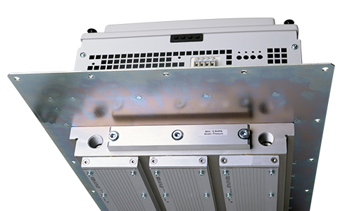
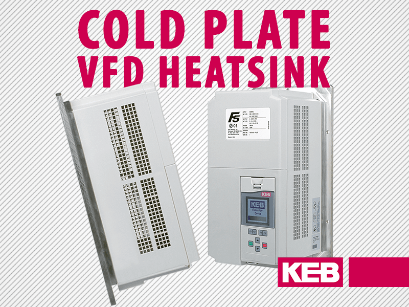
Choose Liquid Cooling
A final option is to not rely on air as the cooling medium. It might be possible to use a liquid-cooled VFD instead. In this scenario, fluid like water or glycol is cycled through the drives heatsink. It should be noted that the pump and radiator will still need to be sized to handle the required heat dissipation at the target elevation.
Challenge 2 – Creepage and Clearance distances
The second challenge at high elevation is due to what’s called creepage and clearance distances. During the design phase of the PCB, the conductors are separated from each other to ensure there is no arcing between the traces. The distance of the dielectric material (PCB or air) insulates the conductors from each other. The distance of separation on the PCB is referred to as the creepage distance. The distance of separation through the air is called the clearance distance.
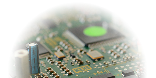
In short, the dielectric properties of the air change with altitude – specifically the air at high altitude does not insulate as well as at sea level. This has significant implications, especially for products involving high voltages like VFDs.
Increase Trace Distances on PCB
So why don’t designers just increase the distances between the traces on a PCB? Because smaller is usually better for most industrial applications and drive manufacturers are always trying to optimize designs and get more output from smaller sizes. Unfortunately, this means there is no easy way to redesign the boards or modify a standard VFD in a way that is usable at very high elevations (e.g. 2000 meters and above).
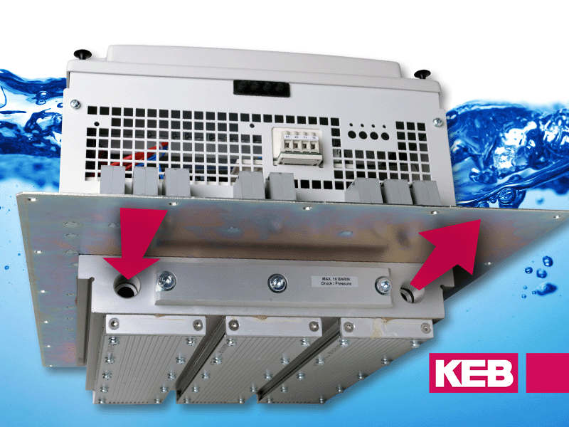
Pressurize the Enclosure
The only option above the maximum defined altitude is to pressurize the enclosure to a suitable level.
Creepage and clearance distances will become increasingly important as VFD manufacturers move from the old UL 508C standards to the new harmonized UL 61800-5-1 standards. UL 61800-5-1 has higher creepage and clearance distance requirements and more stringent investigation of the PCB design. This likely means that drive manufacturers and users have less flexibility than before when applying drives at high elevations. Often times a pressurized enclosure will be required to meet the standard.
Summary
The two main challenges when applying VFDs at high altitudes are reduced cooling capacity and creepage and clearance distances. The reduced cooling can be addressed passively by adjusting the operating parameters or derating the drive. However, additional equipment such as an A/C unit or pressurized cabinet might be needed depending on the application requirements.
Related Articles
Let's Work Together
Connect with us today to learn more about our industrial automation solutions—and how to commission them for your application.