
The F6 drive start-up procedure is straightforward with KEB’s Combivis 6 VFD software. The programming wizards in COMBIVIS 6 allow you to get a motor spinning in minutes.
We will highlight the start-up of an F6-K VFD with sensorless closed loop control (ASCL) without encoder feedback. The general process will be similar for other motor types.
Components for Getting Started
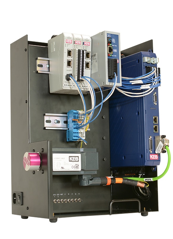
Five main components will be required to start up a motor with an F6 drive.
- Power Source (F6 has options for 1-phase and 3-phase input)
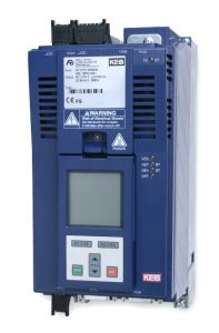
- F6 VFD
- 3-phase AC motor (F6 runs either induction or servo motors)
- Encoder feedback device and encoder cable (unless you’re using ASCL operation)
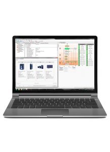
- COMBIVIS 6 software on a computer to configure the VFD
Once the power and devices are correctly connected, we can open COMBIVIS 6 and begin programming.
Getting Connected to COMBIVIS 6
Open a new project in COMBIVIS 6 Software and click the “Scan for KEB Device” Icon.
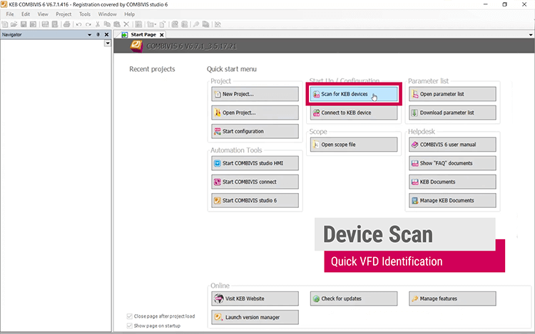
In order to begin programming, we must first connect our drive to COMBIVIS 6 using either the KEB USB-to-serial converter or the keypad with a USB input. Once connected, we can perform a device scan and add the F6-K drive to the COMBIVIS 6 project.
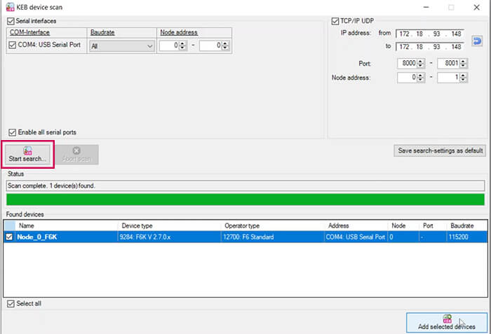
To find the KEB S6 servo drive, simply click on the “Start Search” button. Once you have successfully connected the F6-k drive to your project, you can access the interactive programming wizards that are specifically designed for use with generation 6 VFDs (F6) in the COMBIVIS 6 software.
Now we can take a look at the start-up Wizards Tabs to get your motor spinning.
Steps to Starting a Motor
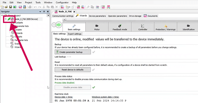
Now that the drive is connected to the COMBIVIS project you can begin the motor startup procedure. The first step is to clear any previous settings in the drive.
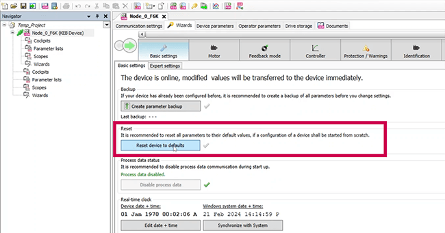
Restore factory default device settings
Let’s start by opening the basic settings tab. From here, select “Reset device to defaults” to wipe any existing programming from the drive and return it to its original factory settings. Even though KEB sends new drives with default settings, it’s always wise to perform this step to ensure you’re starting from scratch.
After the drive resets, let’s go to the Motor tab.
Input motor nameplate data
In the Motor tab, you can input your motor’s rated nameplate data. If you have a KEB motor, you can easily load the rated data from the KEB motor database. After loading the data, you can confirm the motor type and the type plate data below.
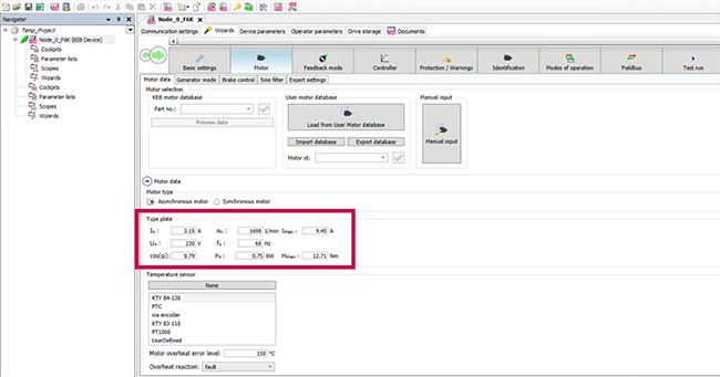
If you’re using a non-KEB motor, select the “Manual Input” button on the right and input your motor’s rated data in the spaces provided.
Next, move to the Brake Control tab. If your motor doesn’t have a brake, deselect the “Activate Brake Control” box. If you do have a brake, you can add timing and source information for the type of brake you’re using.
Enter Feedback Mode
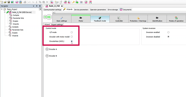
Select the feedback mode you are using.
In the Feedback mode tab, there are three options:
- v/f mode
- Encoder with motor model
- Encoderless (ASCL)
Let’s take the example of selecting Encoderless (ASCL). In case you have an encoder, you will need to provide the encoder information such as speed control source and position control source.
On the right-hand side of the page, you will notice the “System Inversion” section. This feature allows you to invert the motor operation. So, if your machine requires an anti-clockwise rotation but the motor is set to rotate clockwise, you may enable this option to invert the motor operation.
Set Speed Controller Option
Let’s move on to the Controller tab. The speed control of the F6 drive is a PI controller (proportional integral), which means it consists of proportional and integral components.
You can modify the settings by entering values in the designated boxes or using the slide under “Controller performance” to adjust from soft to hard. At the top, you’ll need to input the motor inertia and load inertia.
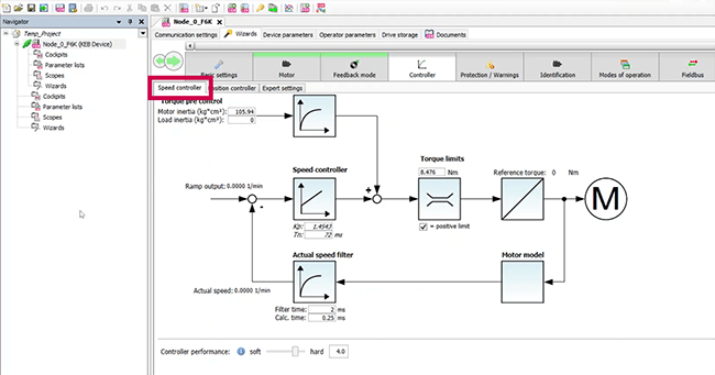
The position controller, on the other hand, is a proportional controller, and you can adjust it on the next tab if necessary.
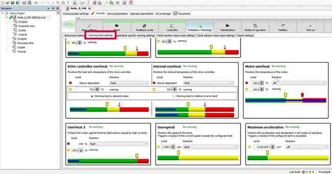
Protections and Warnings Tab
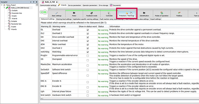
There are several protection features in COMBIVIS 6 to help the drive protect itself, the motor, and the machine as a whole to protect the operation. You can adjust and select a number of protection functions and set specific warning levels. We will not worry about these in our quick startup, but when you integrate the VFD into your machine you will want to set these warning levels as needed.
Motor Identification Process
We start by confirming our rated nameplate data in the Identification tab. Then, a second box appears offering additional detection options.
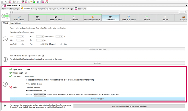
After meeting the four requirements mentioned in the Identification tab, you can start the identification process by clicking on “Start identification.” It is necessary to conduct the identification under no-load conditions for accurate results. To get more precise numbers, allow the motor to rotate. If you are using sensorless closed loop control, you should select “Main induction detection” in step two.
The next step is to set the STO to get a green check mark. In case you don’t have a brake, as in our example, you will see a red “x” next to it in this section, but it’s not a problem for the motor learn process.
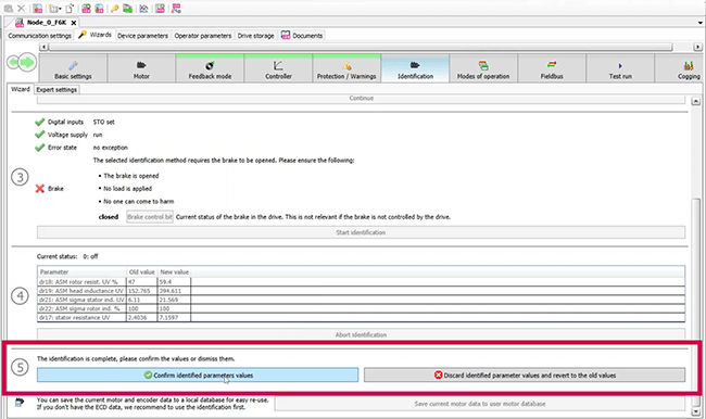
Old and New Values will populate after the motor identification.
During and after the motor identification, a small table will populate with a few motor parameters, the encoder mounting position, and their respective “old” and “new” values. The “old” and “new” values represent the parameter value before and after the identification. Some parameters might differ after the identification, but this is to be expected as the identification now incorporates cabling and other realistic setup characteristics.
Confirm the identified parameters and then move into the Modes of operation tab.
Select Your Mode of Motor Operation
You will see five available modes of operation for this F6 drive in the next tab. You will see “Profile Position,” “Velocity Mode,” “Homing Mode,” “Cyclic Position Mode,” “Cyclic Velocity Mode.” For our testing, we will choose “Velocity mode.” Once selected you can adjust the forward and reverse acceleration.
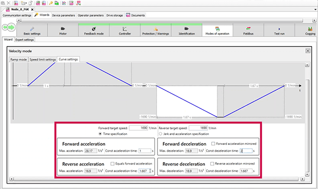
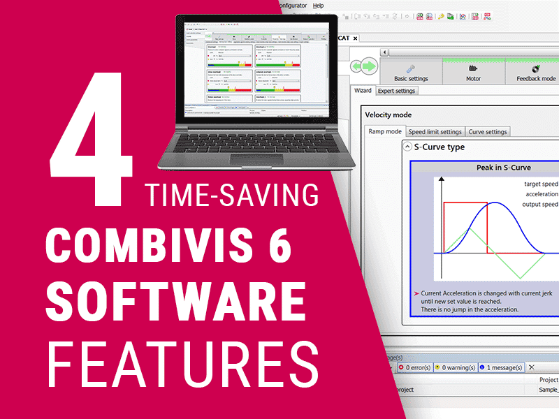
Choose ramp mode and speed limit settings
Once you select “Velocity mode,” a Velocity mode pop-up will appear. The ramp mode tab is where you can select between S-curve and linear ramp profiles. In the Speed limit settings tab, you can set your maximum and minimum velocities in each rotation direction.
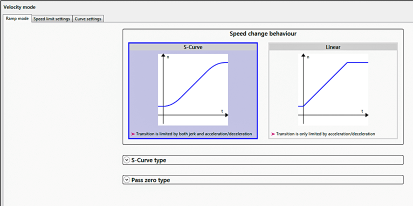
When you select your speeds, click the “X” at the top of the Velocity mode pop-up to close the window.
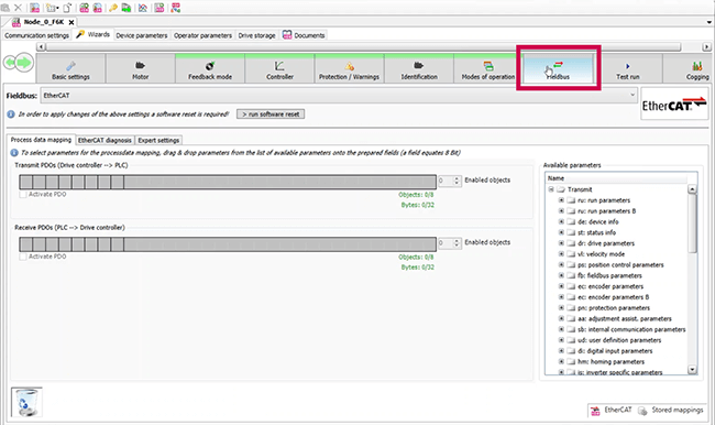
Fieldbus Options
You can select which fieldbus to use in the Fieldbus tab. By default, KEB drives operate in EtherCAT communication, but you can choose the fieldbus from KEB’s large variety of fieldbus options.
Perform Motor Test Run
When you select the Test Run tab you can click the Start ‘test run’ wizard in the center of the screen to launch the test run dashboard.
Set the target velocity of your motor. At the top of the test run wizard are four preconditions for running, which were the same prerequisites for the motor identification. In this example, there is no brake to control so the brake can remain closed.
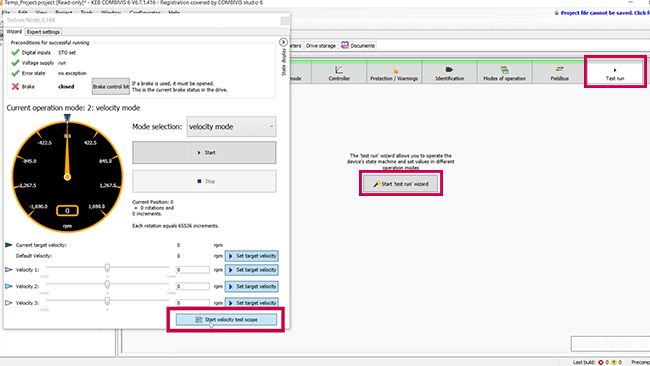
After you set target velocity, click the start button to move the motor. Set the speed in the “Velocity 1” text box, you can select the “Set target velocity” button. Click “Start” when you are ready to spin the motor. The motor will spin and the encoder speed will be tracked on the speedometer.
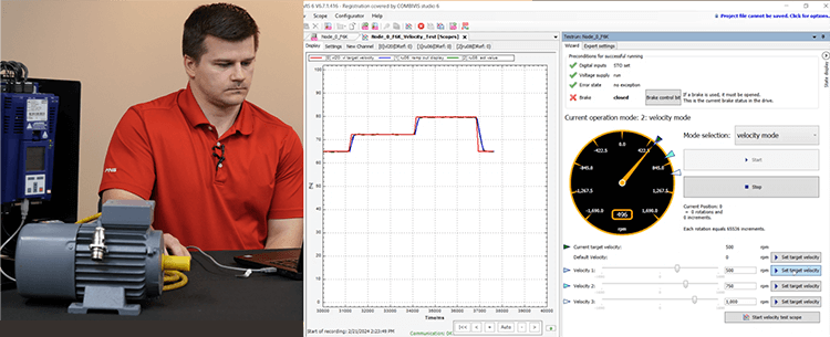
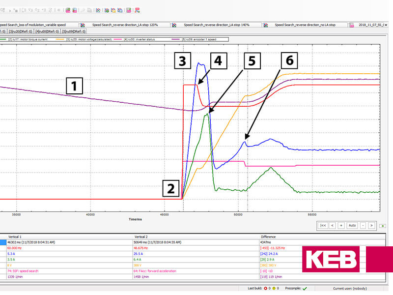
To stop the motor, simply click on the Stop button located in the test run window. Additionally, COMBIVIS 6 comes equipped with a 16-channel Oscilloscope that allows you to track parameters such as speed, current, and other relevant metrics. You can conveniently move these parameters around within the COMBIVIS window to display them side-by-side, similar to the image shown above.
Congratulations
You’re now up and running!
COMBIVIS 6 Wizards offer so many other features that we did not explore at this time. It’s crucial to thoroughly navigate through all the function sections to finalize the commissioning of your drive and motor for seamless integration into your industrial machinery.
If you want to learn more, fill out the form below to contact a KEB engineer today.
Related Articles
Let's Work Together
Connect with us today to learn more about our industrial automation solutions—and how to commission them for your application.