
Uninterruptible power supply and regenerative energy in elevator applications
This post describes how to implement an uninterruptible power supply in elevator applications using KEB’s R6 line regen drive and VFD.
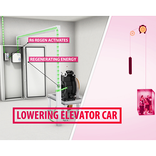
Advantages of VFD regenerative drive
Regenerative drives are an excellent option for elevator or lift applications since the motor is acting as a generator for roughly half of its use. Before regen drives were available, excess DC bus voltage from the drive unit was dumped across a braking resistor, generating additional heat in the machine room. While this method of energy transfer is simple, all excess energy is turned to heat, which can add to machine room cooling costs. By regenerating the energy back to line, building owners and operators can save a substantial amount of money, often times paying for the regen drive within a few years. To see how much money a KEB R6 line regenerative drive could save you, try out our custom ROI calculator.

Uninterruptible power supply and regenerative energy
Buildings that feature an uninterrupted power supply pose a unique situation when it comes to using a regen drive. The UPS is used to provide power to the elevator and controller in an event of a power outage. Regenerating A/C current back to the UPS, while active, is not an option because the UPS is essentially a large DC battery and regening back to this DC supply could cause damage. However, for building owners and operators that still want to realize the cost savings of a regen drive, it is possible to implement a regen drive alongside a UPS.
Application note
A line regen can be used with a UPS as long as the line regen is disabled while the UPS is active. This can be accomplished by having a relay contact open the R6 enable, pin 12 on terminal strip X2A, while the UPS is activated. Additionally, another relay contact can activate an external fault condition, pin 15 on terminal strip X2A, to further prevent modulation by the R6 unit. This setup features dual level redundancy that ensures the regen unit stays in “passive” state and does not modulate/regenerate back to the UPS unit. The regen still acts as the rectifier though, even without the enable signal, supplying the drive unit to in order to continue to drive the motor under backup operation. Below is a wiring diagram showing this setup.
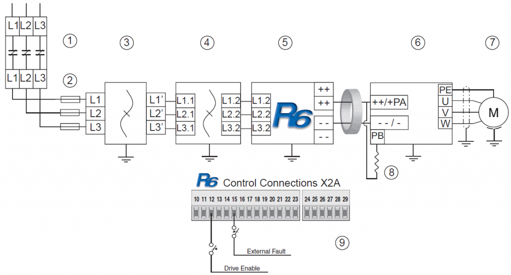
Any excess DC bus voltage regenerated by the motor when the regen unit is disabled can be dissipated through a braking resistor on the VFD unit during UPS operation. An additional contactor to deactivate the braking resistor under normal operation is not needed since the regen unit would normally begin to modulate (at 103% of the nominal idle DC bus voltage; approx. 334VDC for a 230V unit and approx. 668VDC for a 460V unit) at a lower DC bus value than when the braking transistor would turn on at much higher level (380VDC for a 230V unit and 760VDC for a 460V unit) and dumping the excess DC bus voltage across the resistor.
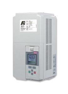
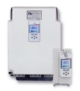
R6 – Regen Drive for VFD Applications
For more information on the KEB R6 line regenerative drive, please contact a KEB America engineer for an overview of features and available options that can best fit your application.
Related Articles

Let's Work Together
Connect with us today to learn more about our industrial automation solutions—and how to commission them for your application.