
What are the Main Components of a VFD?
The components of a VFD (Variable Frequency Drive) consist of two main sections – the power stage and the control circuit.
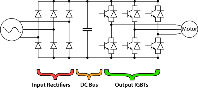
Previous videos on KEB’s YouTube page show how the input rectifiers, DC bus capacitors, and output IGBTs sections of the power stage convert the AC line voltage to a Variable Voltage Variable Frequency (VVVF) AC output to the motor. In a previous lightboard video, we discuss the control circuit which handles logic and can be considered the brains of the drive.
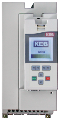
On KEB’s F5 drive, the control card has a few main components. The first is the internal connection to the power stage. This allows the control to tell the power side when and what to output to the motor.
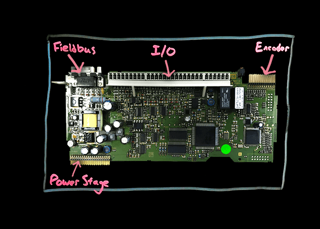
Next, are the analog and digital inputs and outputs (2). These are used for simple, logic-based control. On the F5 drive, there are two analog inputs, two analog outputs, eight digital inputs, two digital outputs, and two relay outputs. All of these can be programmable to do a variety of different functions. For example, an analog input can accept a 0-10V signal to control the command speed or a digital output could send a 24V signal to indicate the actual speed has reached the command speed. Using just the terminal I/O, the drive can use basic logic to interact with the rest of the machine and know how to control the motor.
For more advanced control, the control circuit uses optional, modular fieldbus operators. These are used for real-time communication and control with a PLC. KEB’s standard protocol is EtherCAT, but all major protocols such as EthernetIP and Profinet, are supported and easily integrated into the drive control. Using the fieldbus, the PLC can control the drive and get nearly instantaneous feedback about how it is performing.
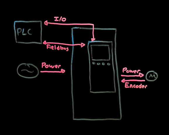
The final component of the control card is the optional, modular feedback cards. This allows the drive to accept feedback from the motor in order to run in closed-loop control for precise speed and torque control of the motor. On the F5 drive, two channels are available, and all major protocols such as TTL, Resolver, SinCos, etc. are accepted.
In summary, the power stage and control circuit are the two main components of a VFD. Hopefully, you are a little more familiar with the main components of a drive and how they are used to interact with the rest of the machine and control the motor. If you have further questions, please contact us via the form below.
Related Articles
Let's Work Together
Connect with us today to learn more about our industrial automation solutions—and how to commission them for your application.