
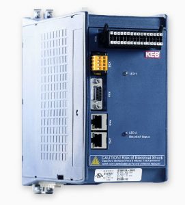
Setup Guide: G6 IO Link Communication with a Turck EtherCAT Slave/IO-Link Master
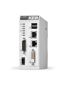
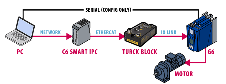
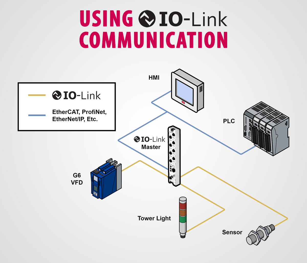
This post overviews the setup of communication between a Turck BL Compact Fieldbus Station for EtherCAT and KEB’s G6 open-loop VFD. The G6 VFD is capable of operating both induction (asynchronous) motors as well as servo (synchronous) motors without motor feedback. The EtherCAT master in this example will be KEB’s C6 Smart PLC, sending speed commands to the VFD through the IO-Link protocol via the Turck IO-Link Master. See this blog for a brief overview of the IO-Link protocol utilized in this solution.
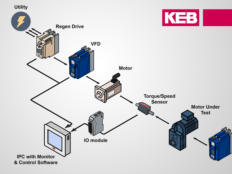
To see this solution in action, you can follow along with the video below.
1. Connect to the G6 VFD
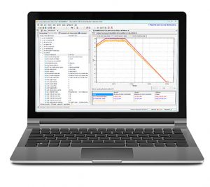
The process data of the G6 must first be configured in KEB’s free Combivis 6 VFD software.
To configure the G6 Drive, connect your PC with KEB’s USB-serial cable to the X4A port of the VFD. Next, use the KEB device scan tool to search for the device on the KEB DIN66019II Communication Port.
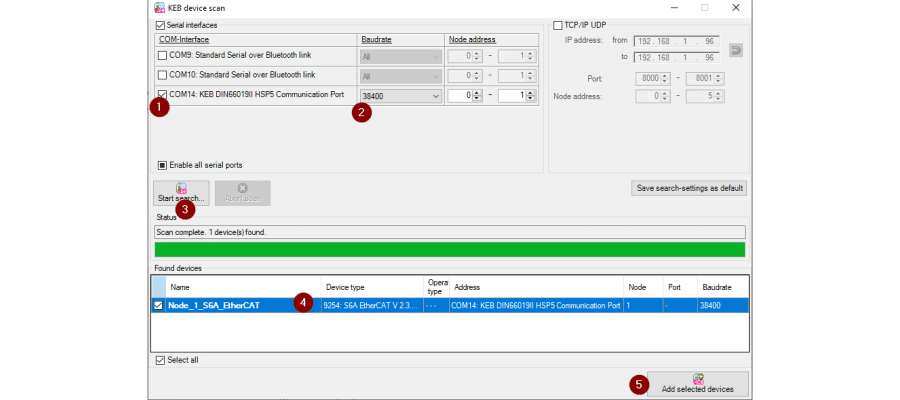
To scan, (1) select the KEB DIN66019II HSP5 Communication Port interface, (2) narrow the search to a baud rate of 38400, (3) start the search, (4) select the device, then (5) hit Add Selected Devices.
2. G6 VFD Process Data Configuration
The process data of the G6 must first be configured in KEB’s free Combivis 6 VFD software.
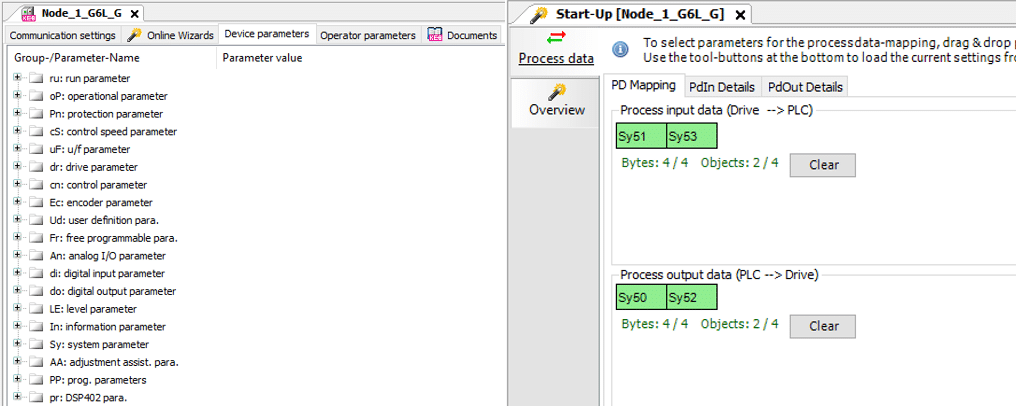
The process data of the G6 is limited to four bytes in/four bytes out with an object limit of four combined. To set the process data, locate the parameter to be exchanged by double-clicking on the G6 drive in the Navigator and going to Device Parameters. The parameter of interest can then be dragged into the Process Data tab of the Start-Up wizard into an empty slot in the Process Input Data or Process Output Data. The output parameters used are Sy50 – control word and Sy52 – set speed value. The input parameters used in this example are Sy51 – status word and Sy53 – actual speed value. To set the process data mapping in the drive, select Download in the same tab.

3. Additional drive parameters
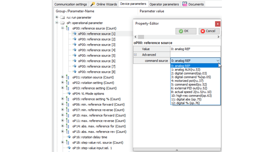
To use the process data parameters defined in the previous step, parameter oP00 – reference source should be set to a value of “5: command speed(sy.52)”. Parameter op01 – rotation source should be set to a value of “10: RUN/STOP control word (sy. 50)”. These parameters ensure that the Process Output Data defined in the previous step will be used to run/stop the VFD as well as set its command speed. These parameters may be set in the Device Parameters tab.
Depending on the type of motor being operated as well as the control type (settable in the Online Wizard or by parameter Ud02), additional G6 parameters should be set for smooth motor operation.
To operate an asynchronous motor in V//Hz mode (done in the video example), the motor nameplate data is not necessary except for the rated frequency, which is set by parameter uF00.
To operate an asynchronous or synchronous motor in ASCL or SCL mode, respectively, enter the motor nameplate data in the dr parameter group. You can keep up to eight sets of certain parameters in the drive, with the default set being [1], unless otherwise set by the control word.
It is good practice to save any parameters that you change to a parameter list. This list can either live inside the Studio 6 project or be saved as a .dw5 file to your PC. This saves time in the future if the drive is ever swapped out or if a factory reset is performed.
4. Create a PLC project shell
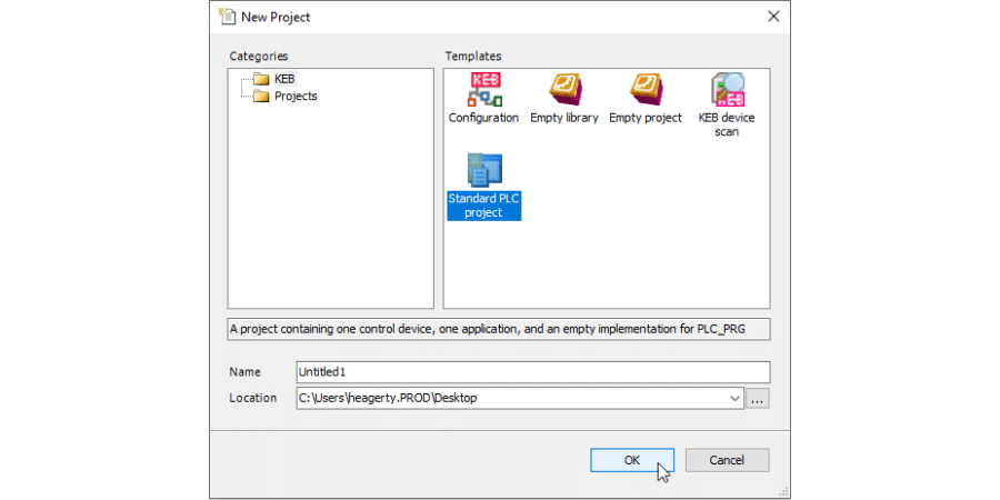
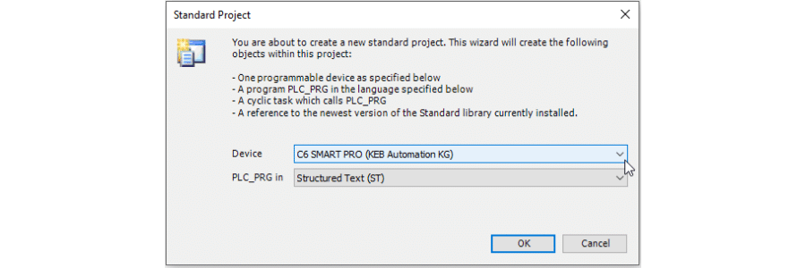
With the EtherCAT master used in this setup being KEB’s C6 Smart PLC, the PLC project will be developed in KEB’s Combivis Studio 6 environment. The drive configuration tool used in the previous step is also wrapped into Combivis Studio 6. In Studio 6, start a new project by navigating to File > New Project. In the popup window, select the Standard PLC Project template, define a name and location, at hit OK.
In the next window, select the device that will receive the logic, a C6 Smart in this example, as well as your preferred IEC 61131-3 implementation language for the main program. Select OK.
An application template will be created and be visible in the Navigator window. Finally, right-click on the device in the Navigator, select Add Device, then locate the EtherCAT Master of the C6 Smart PLC.
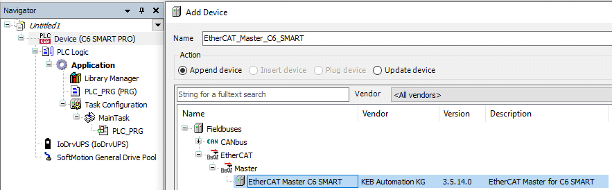
The Navigator will now be updated with the EtherCAT Master shown. Since the C6 Smart also has a coupler for DIN rail-mounted device on the side, a coupler device is also added. Next, we need to add the Turck EtherCAT slave to the EtherCAT tree that we have started.
5. Import Turck Device and Add to Project
The configuration XML file used by the EtherCAT master for configuring the Turck IO-Link station may be obtained from this page under Download > Configuration File. Save this configuration file to your PC. In Studio 6, navigate to Tools > Device Repository. Select Install, then locate the configuration file. The Turck IO-Link station is now available to use in the environment. To add the EtherCAT slave to the project, right-click on the EtherCAT master in the Navigator, select Add Device, then locate the device and select Add Device.
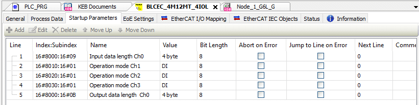
6. Configure device startup parameters
Pictured below are the five startup parameters that must be set in order to configure the BL compact’s handling of the IO-Link data. Firstly, the input and output data length of the channel being used, channel 0 (Ch0) in this case, must be set. Since the process data of the G6 is set to four bytes in/four bytes out, these are each set to a value of “4 Byte”. Secondly, the other available IO-Link channels (channels 1-3 in this case) must be configured to not expect IO-Link communication. This is commonly done by setting them to be digital input (DI) channels instead of their default IO-Link functionality.
7. Configure the device EtherCAT I/O Mapping
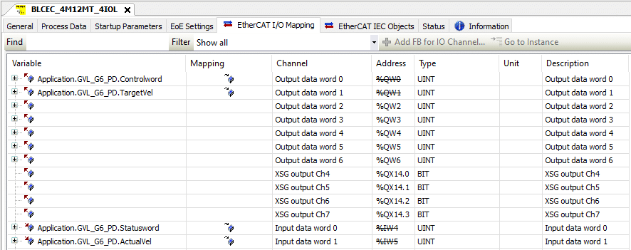
The variable mapping may then be configured under the EtherCAT I/O Mapping tab of the Turck device. Since we have one channel being used with four bytes (two words) of output data and four bytes (two words) of input data, the variables are mapped to Output data word 0, Output data word 1, Input data word 0, and Input data word 1. See the example below.
The “Always update variables” field in the EtherCAT I/O Mapping screen should also be set to “Enabled 2 (always in bus cycle task)”.
8. Start the PLC project and Test Communication
Login to the C6 Smart and run the PLC project. To do this, first ensure that the Codesys Gateway is running on your PC. A running gateway is denoted by a red icon on your PC’s taskbar.

Next, (1) go to the C6 Smart device in the Navigator, (2) in the Communication Settings tab, add the gateway if it is not already there, (3) scan the network for the PLC, (4) select the device under the gateway and Set Active Path, (5) login to the device, and (6) run the program.
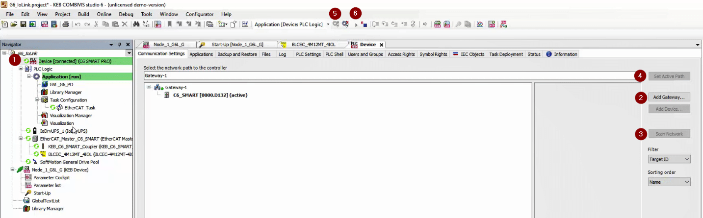
A successful EtherCAT run is shown by all-green icons next to devices in the Navigator window.
To test the parameter exchange between the PLC and the VFD, write the variables corresponding to the process data output (controlword and target velocity in this example), and verify their values in the drive parameters through the serial connection. Likewise, compare the process data input parameters in the drive to their corresponding variable values in the PLC. For safety, this communication with the VFD should be tested before a motor is connected.
Additional Information
Although a control/status word and command/actual speed are sufficient process data parameters to run the G6, further drive information may be desired to monitor things like fault status, motor voltage, internal drive temperature, etc. The G6 drive has the ability to communicate extra parameters through an acyclic channel. However, the IO-Link master used in this setup cannot handle this communication.
KEB’s G6 VFD offers a great low-cost solution for high-speed applications, especially in systems where IO-Link devices are utilized. The C6 Smart PLC’s quick and easy setup in COMBIVIS Studio 6 also makes for quick and easy setup of the Turck IO-Link device utilized in this example.
Contact an application engineer today to learn more about the KEB products used in this solution!
Related Articles
Let's Work Together
Connect with us today to learn more about our industrial automation solutions—and how to commission them for your application.