
3 Ways to Protect a VFD Braking Resistor from Short-Circuit Failure
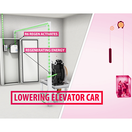
Energy overload situations can cause braking resistor failure but can be easily prevented with the right equipment and system design. In this article, we’ll explain the cause of overload conditions and present three methods that will help you address this common problem. After all, you want to protect your VFD and related equipment in order to prevent unhappy customers and co-workers who experience a system failure.
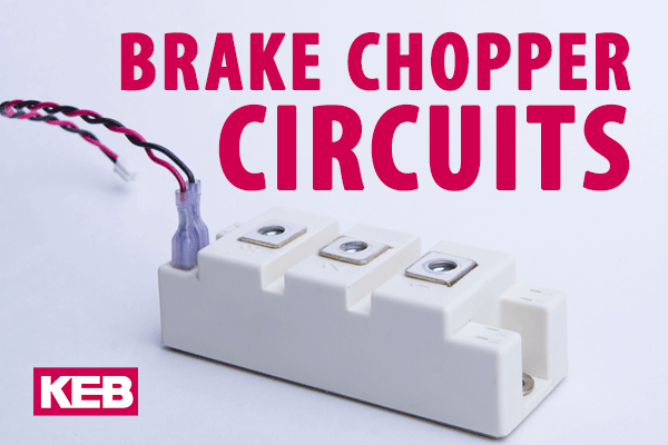
Brake Resistor – Normal Operation
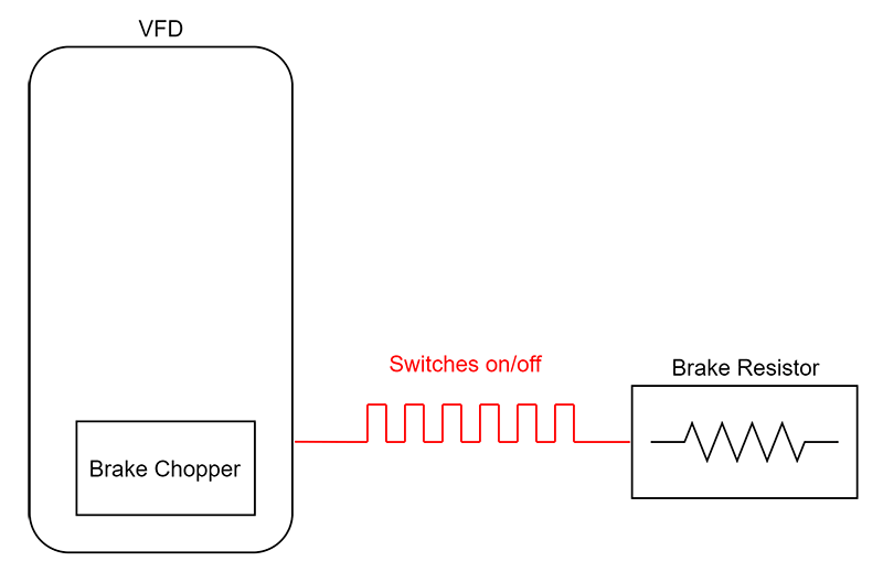
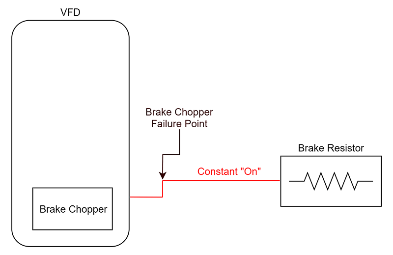
Under normal operation, the brake resistor is driven by a brake chopper transistor when excess energy is returned to the VFD. The brake chopper continuously turns the brake resistor on and off until the extra energy is dissipated. The resistors are sized to be used with a brake chopper and not for direct, continuous connection to the VFD’s DC bus.
What is Brake Chopper Failure?
If a brake chopper fails, it most likely fails in a “shorted” state. During a short-circuit failure, the brake resistor is subsequently connected, unrestricted, to the DC bus voltage of the VFD. As mentioned earlier, the brake resistor is sized to be used with a chopper circuit. Consequently, a direct connection to the DC bus overloads the brake resistor and can cause external damage and also become a fire hazard.
3 Ways to Safeguard a Brake-Resistor from an Overload
There are several options to prevent a braking resistor failure from an overload situation. KEB suggests at least one of these options:
- Brake-Chopper Transistor Monitoring Board
- Installation of Brake Resistors with a Thermal Switch
- Intrinsically-Safe Brake Resistors
1. Brake-Chopper Transistor Monitoring Board
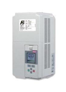
KEB offers an optional monitoring board for various sizes of F5 VFDs. This board monitors for short-circuit failures within the brake chopper circuit. When a brake chopper malfunction is detected, a drive fault is generated that triggers a dedicated form C relay. The control system should be designed in such a way that power is removed from the drive or resistor when this relay is opened.
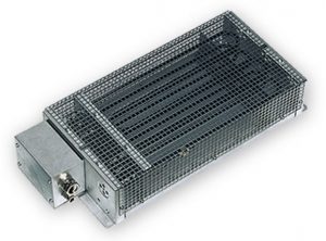
2. Brake Resistors with a Thermal Switch
Brake resistors can be equipped with a thermal switch to detect a potential overload condition. When a resistor is overloaded, it attempts to dissipate more heat than it was designed to do. In this case, the thermal switch will open when the temperature of the resistor becomes too hot. KEB recommends interrupting one of the high voltage supplies to either the VFD or the resistor. Refer to the next 2 diagrams on how this can be implemented.
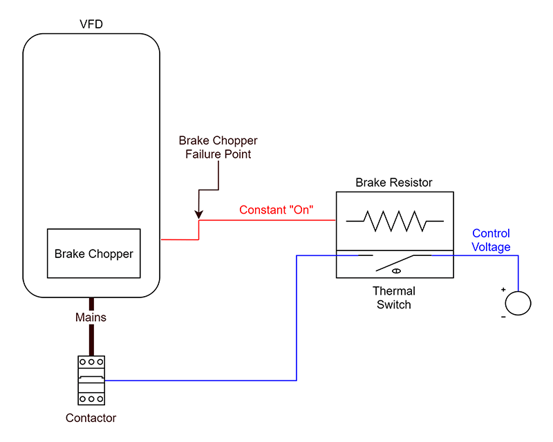
Above: The thermal switch opens from excessive heat. The control voltage used to close the mains contactor is interrupted. This opens the main contactor and removes power from the VFD.
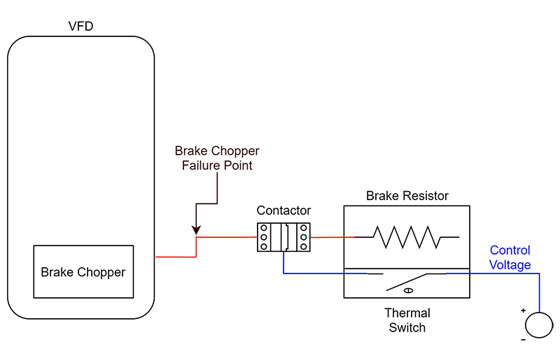
Above: The thermal switch opens from excessive heat. The control voltage used to close the contactor to the braking resistor is interrupted. This opens the contactor and removes power from the braking resistor while the VFD remains powered.
3. Intrinsically-Safe Braking Resistors
KEB also offers braking resistors that are intrinsically safe. These resistors come equipped with internal overload protection that will open, similar to a fuse, when overloaded. This option does not require any additional hardware or control devices as the protection is built-in to the resistor.
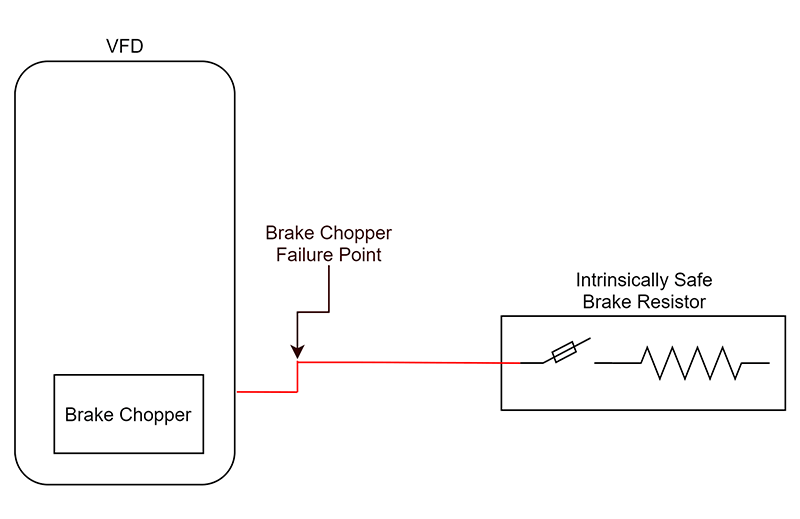
Above: The resistor’s internal safety mechanism has opened due to overload. This safety feature behaves similarly to a fuse. No extra hardware is required for this type of resistor.
Related Articles
Let's Work Together
Connect with us today to learn more about our industrial automation solutions—and how to commission them for your application.