
Ground Fault Nuisance Tripping in VFD Applications
Overview of a VFD Ground Fault
Ground faults are characterized by the accidental connection of a live circuit to a grounded conductor. If the ground connection is solid enough there is a potential for extremely high currents flowing through the live circuits to ground. The current may be high enough to trip any upstream breakers or blow fuses. Tripping breakers or blowing fuses should render the machinery where the ground connection was made safe to personnel.
Unfortunately, for many ground faults the accidental connection to ground has a high enough electrical resistance that excessive currents do not flow. The lower ground current does not trip breakers nor would fuses blow leaving grounded connections energized and dangerous to personnel. For many large installations, a resistor is added to the grounding circuit preventing any ground faults from causing an over-current.
Read the article: 7 Steps to Reduce EMI in VFD Applications
Known as high resistance grounding a ground resistor is installed between the neutral point of a wye connected supply transformer and earth ground Figure 1. The resistor is added to mitigate the hazards that ground faults present. Ground faults can cause dangerous arc flashes and can lead to long system downtimes. High resistance grounding reduces the risk of arc flash events, reduces line-voltage dip during ground fault events, and lowers electrical and mechanical stresses of components during ground fault events (Michael D. Seal, P.E., GE Senior Specification Engineer, 2008).
In the event of a ground fault, current from the faulted machine flows through its ground connection through the ground resistor and into the neutral point of the transformer. In place of a breaker trip or a fuse blown, ground fault protection is provided by a residual current device (RCD).
RCDs are installed to monitor ground currents and disconnect power when a threshold of current is reached thus the RCD covers a critical fault blind spot to systems that solely employ breakers and fuses for fault protection. While the RCDs installed in machinery have improved safety, its application paired with Variable Frequency Drives (VFDs) has led to increasing nuisance tripping and system downtime. This article is intended to aid the engineer when dealing with applications that involve RCDs, high resistance grounded systems and VFDs.
What are Residual Current Devices?
Whether one is aware of it or not, most people have used ground fault protection devices that are installed in their homes. In the U.S. and
Canada, these devices are known as Ground Fault Circuit Interrupters (GFCI); building codes in the U.S. and Canada have had GFCI requirements since 1971. They are installed wherever it is more likely a person could touch a live circuit to ground, such as near sinks or case-grounded appliances. The inner workings of a GFCI are the same as an RCD and can be seen in Figure 2.
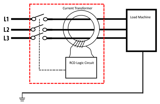
An RCD or GFCI device uses a current transformer (CT) to measure the net current flowing through the line conductors. It can be assumed that any current that does not flow through the line conductors is flowing through the earth ground. Therefore, if the net current through the RCDs CT is above some threshold, the RCD will trip removing power. RCDs are offered with three or four-wire variants for three-phase systems and three-phase with neutral systems. The four-wire variant allows current to flow between a phase and neutral without tripping the RCD.
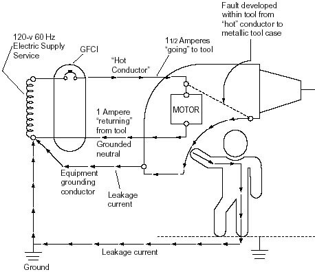
From the Occupational Safety and Health Administration’s (OSHA) website, one can see an example of unwanted ground current through a person in Figure 3. The figure shows a ground fault where the “hot” line of the single-phase 120V supply is connected to the grounded case of a tool. The fault causes the metal case of the tool to become live, when the tool operator touches the tool, the operator receives a shock. Fortunately, the tool is plugged into a GFCI outlet. While the “hot” conductor is supplying 1.5 amperes of current, only one ampere of current is returning through the neutral conductor. The ½ ampere difference will be detected by the GFCI and cause the GFCI to disconnect power, thus saving the tool operator from further injury.
(Image from OSHA (Occupational Safety & Health Administration), 1998)
Leakage Current in VFD Applications
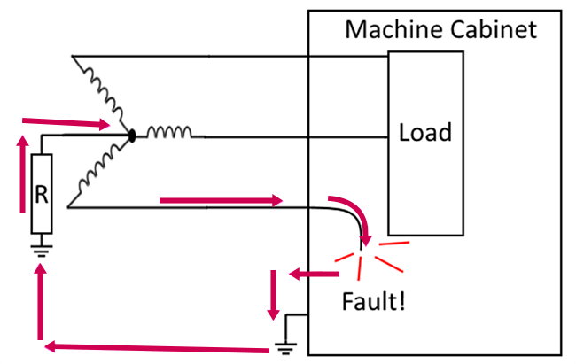
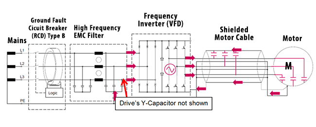
Not all ground currents are due to faults; for most industrial applications ground currents are unavoidable. Ideal three-phase electrical systems are perfectly balanced they can be characterized as a system where all of the electrical currents are carried through the three-phase conductors and no current flows through ground. In a practical circuit, there is always some current that flows through ground during regular operation. This is due to capacitive coupling between current-carrying conductors and grounded elements as shown in Figure 4. These grounded elements can be metal conduits, motor frames, machine cabinets, etc. Current flow through capacitive coupling to ground is exacerbated by the increased uses of VFDs. This is due to the higher frequency currents that VFDs produce. A capacitor’s impedance to current flow is inversely proportional to the frequency of the current flowing through it; this means the higher frequency currents caused by fast switching semiconductors, like those in VFDs, more easily flow through the capacitive couplings to ground. The increased ground current caused during the normal operation of these switching devices can be interpreted by an RCD as a ground fault and causing the RCD to trip. The risk of nuisance tripping RCDs is addressed in the industry by both managing leakage currents and upgrading RCDs to models resilient to the high-frequency current produced by VFDs.
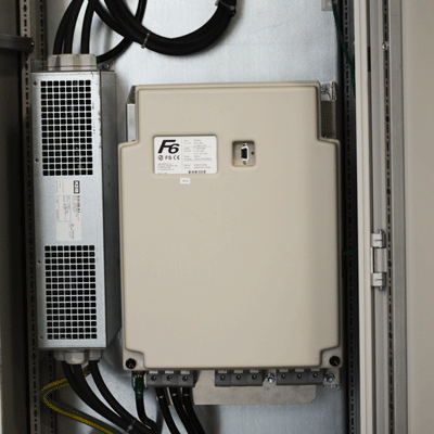
KEB’s drives feature decoupling X and Y rated capacitors [1] between the phases and phases to ground to provide a return path for ground currents before they reach the RCD installed upstream of the drive. High-frequency currents generated by the VFD’s rapidly switching output travel through the motor cables and motor case to ground; then returns to the drive via the Y-capacitor. For most applications, the decoupling capacitors installed within KEB’s drives are sufficient to prevent an excess of ground current from leaking back into the machine’s electrical system. For many applications where controlling leakage current is more critical or multiple drives are used, the inclusion of KEB’s E6 series of filters becomes necessary. The E6 series of filters include larger decoupling capacitors between the phases and ground. The greater capacitance provides a lower impedance path for ground currents to return to the VFD.
[1] Y- Capacitors are designed to fail as an open circuit. This property makes them ideal for decoupling power phases to ground. X-Capacitors are designed to fail as a closed-circuit shorting two phases causing an overcurrent fault.
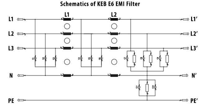
KEB’s E6 series filters are constructed to provide common-mode inductance to each phase as well as capacitive coupling between the phases and each phase and ground. Some of KEB’s E6 filters such as the 14E6T60-4100 provide a neutral connection so they can be paired with four-wire RCDs in four-wire systems. Figure 5 shows a schematic of a 14E6T60-4100 from its datasheet.
Supply-Side Leakage Current and Mitigation
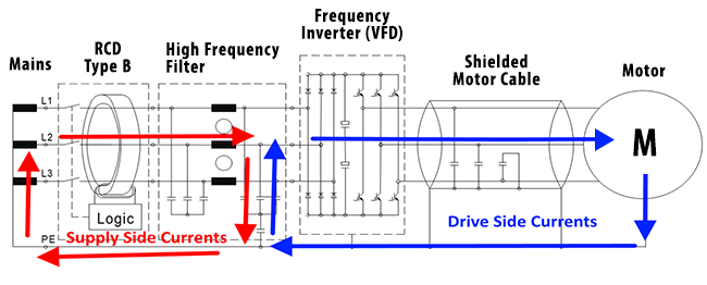
There is a drawback to decreasing the total impedance to ground. As the impedance to ground lowers, the amount of current to ground introduced from the supply-side of the circuit increases. The supply-side ground loop is shown in Figure 6. This ground current flows in from the supply through the RCD and EMC-Filter and returns to the branch circuit’s ground connection. Supply-side and drive-side currents are shown in Figure 6.
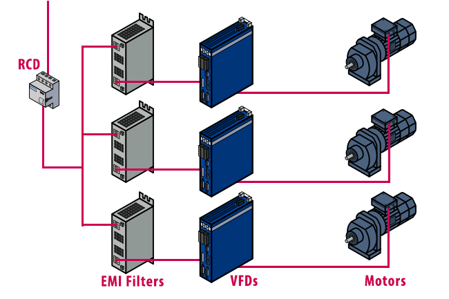
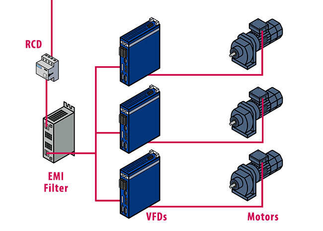
This increased supply-side ground current risks tripping the RCD during normal operation. Making matters worse, many machines have multiple drives installed and an inexperienced machine designer may install an E6 filter for every drive in the machine as shown in Figure 7. The cumulative leakage current through each filter increases the chance of tripping the RCD. To prevent the increase in leakage current, a single filter should supply power to the group of drives. The single filter will offer a lower impedance path for drive-side high-frequency currents to return to the drive, while having a high enough impedance to prevent the flow of excessive supply-side leakage current. A single filter layout is shown in Figure 8.
Some VFDs are manufactured with high-frequency filters built-in. The S6 line of drives has an option to exclude the input filter for cases where the input filter would increase leakage current.
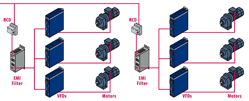
There is a limit to how many drives can be supplied by a single filter. When the total amount of line current from multiple drives exceeds the rated current of the filter, multiple branches with individual RCDs should be installed. The drives should be separated into smaller groups and supplied with their own filters. Each branch is protected by its own RCD as shown in Figure 9.
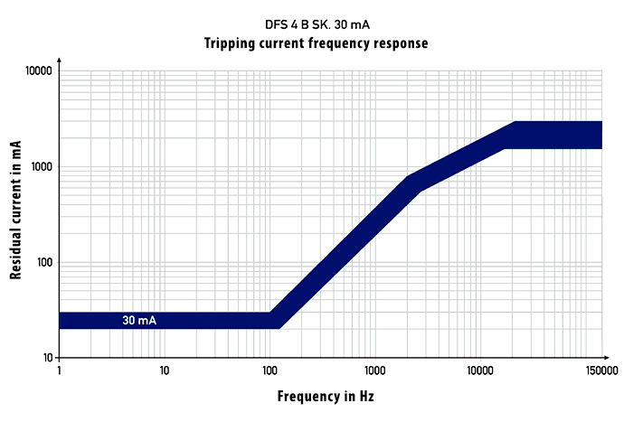
Preventing nuisance tripping can be accomplished by more than a good system layout. Intelligent RCDs can be purchased that have frequency-dependent switching characteristics. The tripping current frequency response of a Doepke DFS 4 063-4 RCD is shown in Figure 10, the allowable ground current increases as the frequency increases. This makes the RCD more tolerant to the high-frequency ground currents VFDs produce during normal operation.
In conclusion, there are a number of factors to consider when working with systems that use RCDs and VFDs together. The increased ground current VFDs produce must be considered to prevent nuisance ground fault tripping. Sound machine design and layout significantly reduce ground current issues. If ground current leakage remains an issue the careful employment of E6 filters along with intelligent RCDs can be used. In the end, the mitigation of ground currents increases machine safety and robustness.
Works Cited
Erasmie, D. (n.d.). Reducing of leakage current with filter E6_in work.pptx. Reducing of Leakage Current.
Michael D. Seal, P.E., GE Senior Specification Engineer. (2008). Resistance Grounding System Basics. General Electric.
Occupational Safety & Health Administration. (1998). Grounds-Fault Protection on Construction Sites. Retrieved 07 18, 2019, from OSHA.gov
Related Articles
Let's Work Together
Connect with us today to learn more about our industrial automation solutions—and how to commission them for your application.