
4 Key Factors to Consider When Sizing Servo Motors
Effectively selecting a servo motor involves closely matching the motor’s capabilities with the specific demands of your application, with a focus on key parameters like speed, torque, gear ratio, and load dynamics.
This critical alignment ensures optimal performance in sophisticated motion-controlled environments. Let’s explore how these elements are pivotal, particularly in servo motor sizing, which is more complex than standard AC induction motors.
How to Select a Servo Motor: 4 Key Factors
In choosing the appropriate servomotor, it’s crucial to consider factors such as acceleration, deceleration, and running torque, which directly influence motor speeds. This consideration is often more complex than sizing AC induction motors.
The servomotor’s dynamic control over load speed and position is critical for optimal performance, ensuring precise alignment with system requirements. Conversely, selecting the right servo size demands a focused analysis of your application’s specific load and speed requirements and operational dynamics.
Let’s examine these key factors and how KEB can provide a tailored solution to your motion control needs.
Four key servo selection factors we’ll discuss in detail are:
While there are other factors to consider for your application, these four are most critical when accurately sizing servo motors.
Inertia Matching
Inertia matching refers to the system inertia. Specifically, the ratio between the inertia of the load and the motor. This formula definition is below:

The moment of inertia measures how difficult it is to change the rotating velocity of that object or system. The motor manufacturer should supply the JM (inertia of motor/rotor).
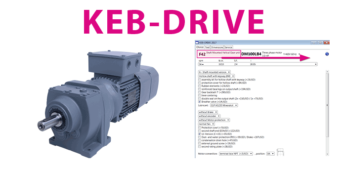
KEB’s servo motor data are found on the KEB drive software, which is a program that aids in choosing motors and gearboxes. JL (load inertia) consists of all components in the system moved by the motor.
This ratio between the motor and load is important when selecting servo motors, but consider the following:
- Performance of the motor improves as the inertia ratio decreases
- Control loop tuning and machine performance improves as the inertia ratio decreases
- A motor with too low of an inertia ratio will be more expensive and have little to no performance improvement
- System inertia ratios should be designed for a max of 10:1 but are typically 5:1 for ideal performance
When choosing and calculating an inertia ratio, find the smallest motor to provide the speed and torque necessary for your application. If you find obtaining a ratio that works challenging, remember that KEB can add additional motor inertia.
Also, many motor manufacturers offer different servo series with different inertias. For example, there might be a product line with a “low inertia” and another with a “medium inertia.”

Speed and Torque Profile
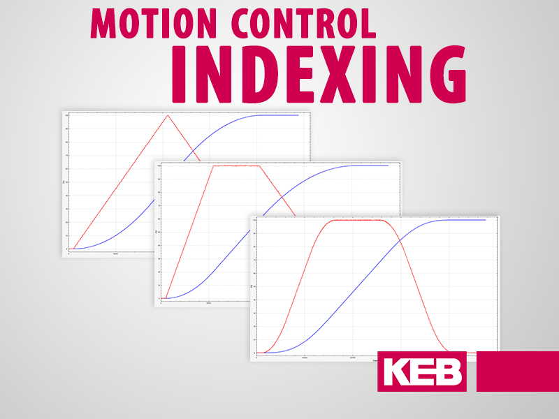
Speed and torque profiles are additional critical elements in choosing a servo motor. While the speed-torque curve describes the motor capability (see below), the application requirements are best illustrated using the speed and torque profile. Depending on the application, there are different speed and torque requirements that the motor will need to meet.
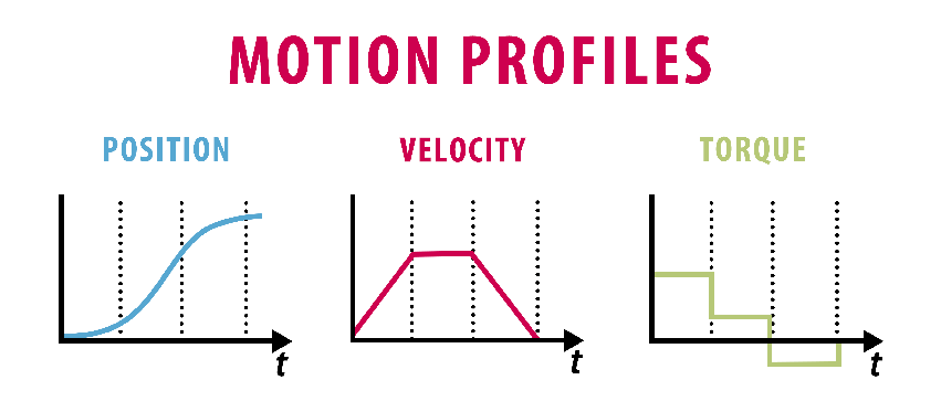
Below is a graphical representation of a linear application with a servo motor. The speed profile represents acceleration, constant speed, and deceleration as the payload reaches its destination. As you can see by the torque profile, the maximum amounts of torque occur during acceleration.
When the machine starts, the motor must overcome the mechanical friction while accelerating the load from rest. Once acceleration is complete, the motor outputs a nominal torque to maintain speed and overcome friction. The decelerating point in the profile is still associated with high torque, but the friction also aids in stopping the load.
Ensuring the motor can produce the required maximum torque at the application speed. This torque ideally falls within the intermittent region of the motor’s speed-torque curve, so it is not oversized.
RMS Torque
RMS torque is the time-weighted torque average during a complete machine cycle (steady state). RMS torque must fall within the continuous region of the speed-torque curve to prevent overheating. Achieving this indicates you have sized your motor correctly.
For example, a servomotor with 4 N·m of RMS torque will experience the same heat rise if it produced 4 N·m of constant torque. Therefore, as long as 4 N·m is in the continuous region of your speed-torque profile, the motor will not overheat.
Speed-Torque Curves
Motor speed-torque curves are essential when selecting and sizing servos. Ensure that the motor has the specific capabilities required for your application to prevent the motor from overheating during use.
These curves ensure that the required torques and speeds (whether continuous or intermittent) can be produced with the servo motor you choose. By examining the speed and torque profiles and computing the RMS torque, you can now look toward speed-torque curves of specific motors and see if they will fit your application.
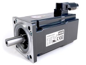
Look at the image below to provide additional insight into speed-torque curves. This image from our KEB drive software will help you decide if your servomotor is valid for your application. This specific image is for our TA3S servomotor.
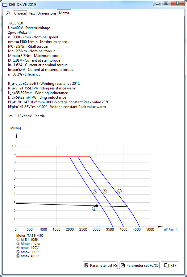
In the image, the blue lines represent the maximum speed/torque based on various input voltages. For this example, we will look at only one input voltage curve, 460 VAC (6).
The region below the S1 line up until line 6 indicates the continuous running region. The servo motor can run at the corresponding speed and torque values without overheating in this region.
Above the S1 line (1) lies the intermittent operation region. In this region, the servo motor can operate for a short time based on the system’s overall RMS torque.
With the input voltage of 460 VAC, the TA3S can reach full peak torque (8.7 N·m) at speeds up to 2750 rpm. This assumes no losses in the drive and that the full 460V is available. If the inverter had an input reactor on the input, there would be a slight voltage drop at the input to the drive, shifting the blue curve to the left.
Related Article: 4 Types of Motor Duty Cycles Every Engineer Should Know
As the speed increases, the available torque starts to drop. If you determine application needs of 4 N·m of torque at 3500 rpm, using 460 VAC would allow you to reach this torque level intermittently. However, with a 400 VAC input, you would not have sufficient voltage to reach this speed and torque.
For continuous operation (rated torque), the required voltage difference is less, so we can reach higher speeds before we enter the field weakening range. With a 460 VAC input, we can achieve continuous rated torque (S1) out to about 4200 rpm.
An important point to remember when using speed-torque curves is to check the input voltage the motor will be operating at and ensure that the motor will run successfully in either the continuous or the intermittent regions.
How Do I Know What Size Servo to Get?
The servo motor size should be capable of handling the peak and nominal running torque demands without compromising efficiency or risking overheating. This requirement is particularly critical during phases of acceleration and deceleration.
To ensure reliable operation, accurately calculate peak and nominal running torque, which plays a vital role in preventing the servo motor from overheating.
Moreover, another pivotal element is achieving optimal inertia matching between the motor and load beyond just the torque requirements. This aspect significantly contributes to the system’s overall response and performance, ensuring the motor is powerful enough and finely tuned to your application’s specific dynamics.
Overall, while considering these technical parameters, size your servo motor in a way that aligns with the specific needs of your application, striking a balance between power, efficiency, and control.
Final Thoughts
While sizing servo motors can be challenging, these four key factors are imperative to making a choice that will fit your application.
If interested, you can download KEB-Drive software from one of the gearmotor product pages. This software includes servo information for the TA servo motors. It also provides information to add inline and right-angle gearing.
Related Articles

Let's Work Together
Connect with us today to learn more about our industrial automation solutions—and how to commission them for your application.