

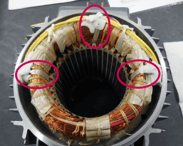
Thermal winding protection for motors is a key component in operational automated equipment. This creates a level of protection against excessive winding temperature that could eventually lead to permanent winding insulation breakdown and failure. EASA has a nice page with some good pictures of typical motor failures – you don’t want this to be you.
Let’s visit a hypothetical example – a manufacturing company utilizes a servo motor on a new assembly machine. The machine begins running well but then the company decides they need faster output, so the motor’s duty cycle is increased. Over time, the higher cycling results in a higher RMS motor current. This higher RMS current accumulates energy in the form of heat inside the motor windings.
The motor eventually begins to overheat. Ultimately, the motor windings fail, and the production line goes down. The motor must be sent to a shop to be rewound or completely replaced. After investigating, the manufacturing company determined that the servo motor did have a PTC thermistor thermal winding protection, but it was not connected to a thermal monitoring source. The failure was completely preventable.
What is Thermal Winding Protection?
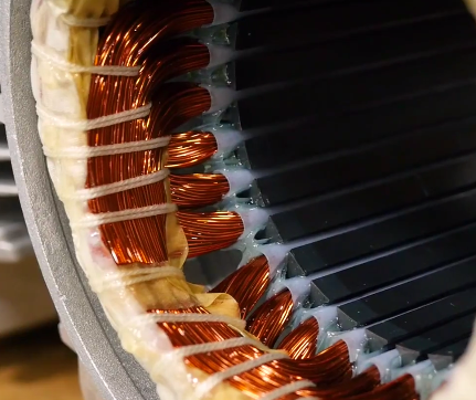
Thermal winding protection can come in several options, but the fundamental principle is the same. The winding protection employs a sensor that registers the thermal condition of the motor’s stator windings. The thermal winding protection causes a motor shutdown when a thermal overload occurs.
Depending on the thermal protection device used, the methodology for thermal measurement and how the protection device interacts with a KEB variable frequency drive (VFD) can be different. We’ll explore some common thermal winding protection devices and temperature sensors here.
Bimetallic Thermal Overload Relay
A bimetallic strip is the operating component of a thermal motor overload relay. Thermal overload relays are one of the most common and economical motor overload protection devices, especially for single-phase motors. As mentioned, thermal overload relays contain a bimetallic strip, and a bimetallic strip is a mechanical device that converts temperature change into mechanical displacement. The bimetallic strip consists of two metal pieces with different thermal expansion rates. The two strips are fixed together by riveting or welding along their length. When heated, the different thermal expansion properties cause the two metals to expand at different rates. This causes the bimetallic strip to bend/flex in one direction if heated above its ambient temperature.
Thermal overload relays are installed in motor circuits, and the current going to the motor passes through the bimetallic tripping element. The flowing current heats the bimetallic strip which causes the bimetallic material to bend, and after a specific temperature, the bimetallic strip will open the relay. Upon opening the relay, the current flowing to the motor will be removed and the motor and motor circuit will be shut down. Thermal overload relays are given a classification called trip class, which represents the response time of an overload condition. Typically, the tripping classes are class 10, 20, or 30.
Thermal overload relays with bimetallic strips are relatively inexpensive and do not require advanced controls to read the information. They are basically binary with ON/OFF states. The downside is that little can be done to react to increasing temperatures before a complete shut-down.
PTC Thermistor Sensor
One common temperature sensor utilized by KEB motors is a PTC thermistor sensor. A PTC sensor is a resistor whose resistance depends on temperature, and the PTC stands for “positive temperature coefficient.” This means that resistance increases with increasing temperature. There are two types of PTC thermistors, linear type, and switching type. The difference between these is based on material, construction, and manufacturing. For this discussion, we will only focus on switching-type PTC thermistors.
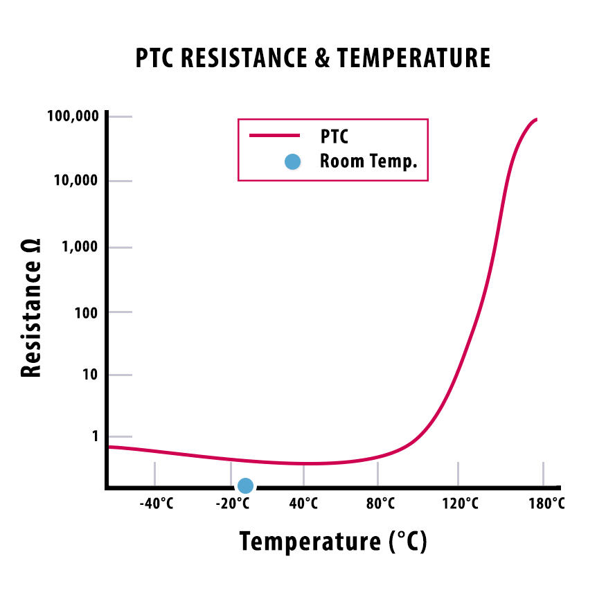
Switching-type PTC thermistors use a polycrystalline ceramic material that has a highly non-linear resistance curve with respect to temperature. Depending on the ambient temperature and resistance, the switching-type PTC thermistor may slightly decrease in resistance with increasing temperature. Still, the resistance response drastically increases at a specific temperature called the critical temperature, TC. The typical critical temperature for a switching-type PTC thermistor is 60°C – 140°C. When the critical temperature is reached, the PTC resistance sharply increases to values over 1,000Ω.
The non-linear characteristic of PTC thermistors is advantageous. In the critical range, a small temperature difference equates to a large resistance change which can be measured and monitored by a VFD or controller.
This high resistance acts as an open circuit, opening the thermal monitoring circuit between the T1 and T2 (or T+ and T-) terminals on a KEB VFD. This open circuit will trigger an E.dOH drive fault, stopping the motor and removing the modulating current. Once the motor and PTC thermistor has been given adequate time to cool down, the motor and PTC thermistor sensor are able to be used again. In this way, the PTC thermistor sensor acts as a resettable fuse.
KTY Temperature Sensor
A KTY temperature sensor is a silicon sensor with a positive temperature coefficient, much like a PTC thermistor. However, the relationship between resistance and temperature for a KTY sensor is approximately linear. The operational temperature range can vary between KTY sensor manufacturers, but typically the range is -50°C to 200°C.
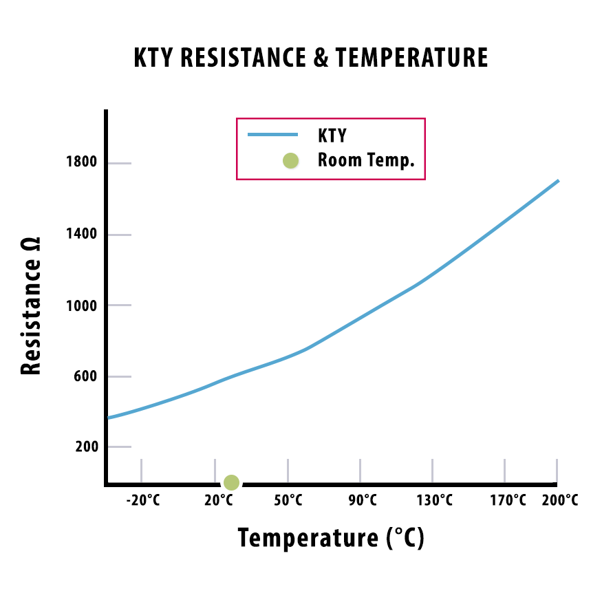
Within the operating temperature range, the resistance response of the sensor can be computed for various temperatures through a second-order equation. Once the resistance is found, a temperature factor can be derived. Using the temperature factor, the temperature at the sensor can be computed using an equation that estimates the approximately linear resistance versus temperature curve.
KTY temperature sensors are increasingly being used in critical applications – especially with large high-investment motors like torque motors and water-cooled motors.
The reason is that KTY sensors allow advanced insights to be gained from the temperature readings. For example, warnings and reduced operational states are more easily implemented due to the accuracy and linearity of the temperature results.
PT1000 Sensor (RTD)
PT1000 sensors are a type of resistance temperature detectors (RTD) or platinum resistance thermometers (PRT) and is maintained by IEC 60751:2008. Many RTD sensors are constructed using a conductive wire wrapped around a ceramic core, and in the case of PT1000 sensors, the wire material is platinum. The PT stands for the platinum wire material and the 1000 represents the resistance in Ohms at 0°C.
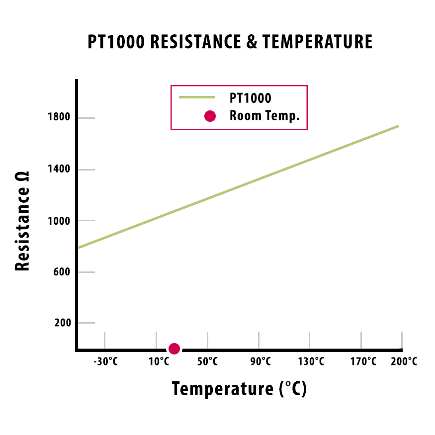
Platinum is employed in RTDs because it has a linear resistance versus temperature relationship, which is highly repeatable over the operating temperature range. The relationship between resistance and temperature is calculated by the Callendar-Van Dusen equation, which can be simplified down to a linear equation. As the platinum sensor is exposed to increasing temperature, the resistance of the platinum increases in direct proportion to the temperature rise. When connected to a KEB VFD, similar to a KTY sensor, the PT1000 sensor can display accurate real-time temperature data of the motor.
Thermal Winding Protection and KEB VFDs
As you can see, many common temperature sensors can serve as thermal winding protection devices for servo and induction motors. However, having a motor fitted with thermal winding protection is only part of the solution. If the thermal winding protection is not connected to a monitoring device or circuit, then the thermal winding protection is irrelevant.
Fortunately, KEB VFDs have a T1 and T2 (or T+ and T-) terminal for the connection of a thermal winding protection sensor. Depending on the sensor type as described above, the drive will be able to monitor the resistance or output the temperature response of the motor windings.
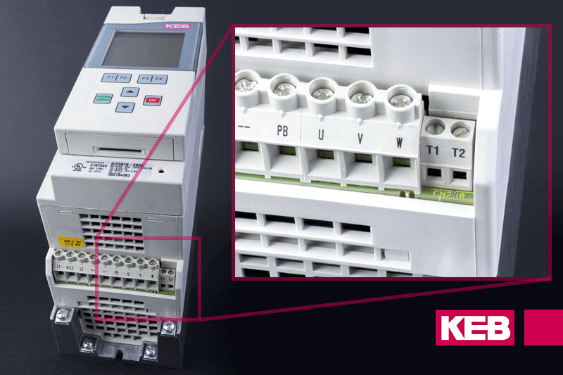
Then, if the motor windings get too hot during operation, the KEB VFD will trigger a fault, which will shut down the motor allowing the motor to cool down to safe operating conditions.
Next Generation Drives and Thermal Protection
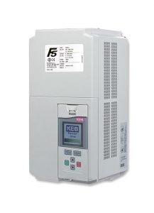
Currently, on our F5 drive series, we can support either KTY or PTC evaluation. We can monitor multiple temperature sensor types in our next-generation F6/S6/G6 product series. For the F6, we can interchangeably monitor PTC, KTY, or PT1000 via a simple parameter change. If a new motor is commissioned and utilizes a different thermal winding protection, the next-generation F6 can easily adapt and support the new sensor type.
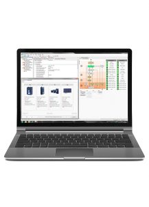
As part of our next-generation series of drives, the F6/S6/G6 family offers unique Online Wizards via our COMBIVIS 6 PC software. Inside these Online Wizards, users can not only set up motor data and operational parameters but can also set limits and reactions to a motor overheating event.
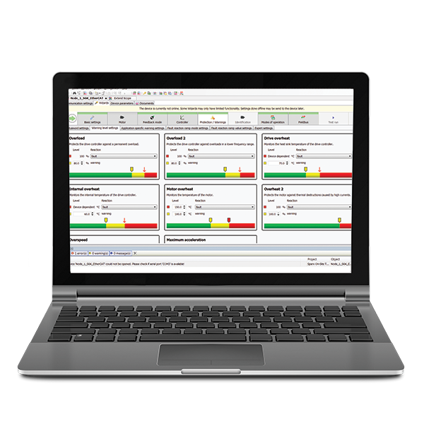
For KTY and PT1000 evaluation, you can set a warning temperature level, an error temperature level, and also adjust the reaction to the error temperature level. Also, in these Online Wizards, you can adjust the temperature sensor evaluation type to match your specific application and motor.
Conclusion
Returning to the example of the manufacturing company from the beginning, what could they have done differently to avoid a failed motor? Using a next-generation KEB VFD such as an F6/S6/G6, they could have installed thermal wiring protection into the KEB T1 and T2 (or T+ and T-) terminals and then adjusted the temperature sensor evaluation to meet their needs. Then, when the motor reaches an overheated state, the drive shuts down the motor, allowing the motor to cool and the manufacturing company to address the overheating issue.

Are you interested in upgrading your automation system with thermal winding protection?
If so, contact us today to discuss this with one of our application engineers.
Resources and further reading:
https://eepower.com/resistor-guide/resistor-types/ptc-thermistor/
https://www.mouser.com/pdfDocs/AAS-PTC-Thermistors-Training.pdf
https://en.wikipedia.org/wiki/Resistance_thermometer
https://en.wikipedia.org/wiki/Bimetallic_strip
https://www.ecmweb.com/content/basics-selecting-overload-relays
http://www.ourdoconline.com/lpcp/1SBC100192C02/mobile/index.html#p=718
Related Articles

Let's Work Together
Connect with us today to learn more about our industrial automation solutions—and how to commission them for your application.