
5 VFD Input and Output Filter Types Engineers Should Know
KEB variable frequency drive (VFD) product line offers many advantages when designed into Control and Automation applications. To achieve maximum operational efficiency and lifetime of the system, installing proper VFD filter types on both the input and output can help achieve this result.
KEB offers a comprehensive range of filters designed specifically for use with VFDs. In this article, we will take a closer look at each type of filter, examine their specific use cases, and highlight the benefits they offer.
Input Filters
Input filters are installed on the incoming power side of the VFD. KEB offers multiple input VFD filter types. Each filter type is designed for a specific purpose, so only one or multiple filters may be required depending on the application requirements.
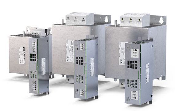
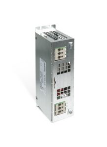
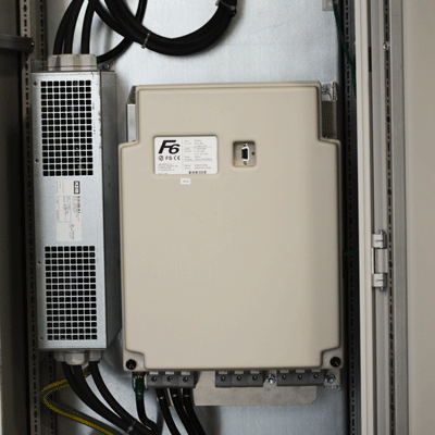
EMI Filter
Electromagnetic interference (EMI) refers to electrical noise with a frequency greater than 30Mhz. Nonlinear components and the PWM switching of output transistors in VFDs can cause unwanted high-frequency noise on the incoming power side of the VFD. The primary purpose of the KEB EMI filter is to block this high frequency noise from transmitting back to the main incoming power line causing issues with sensitive electrical equipment that is powered by the same mains system.
Read More: Introduction to Electromagnetic Interference (EMI) with VFDs
Potential issues from EMI may be PLC or PC communication issues or incorrect readings from sensors or recording devices.
Designing a machine to meet specific industry standards may require an EMI filter. For example, an EMI filter will be required to meet the strict CE requirements for electromagnetic compatibility (EMC), which is necessary for machines operating in the EU. The CE standard defines a maximum EMC level of the system to meet the requirements.
While the EMI filter is a central component of reducing the EMI levels, additional steps may be required to meet the requirements. See the blog post below for more information.
Read More: 7 Steps to Reducing EMI with VFDs
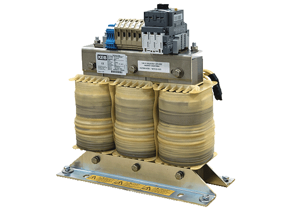
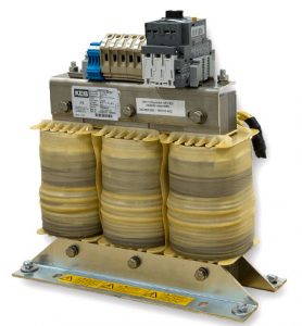
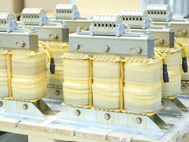
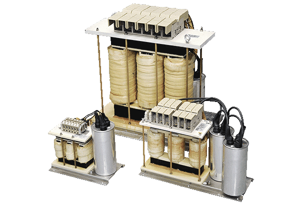
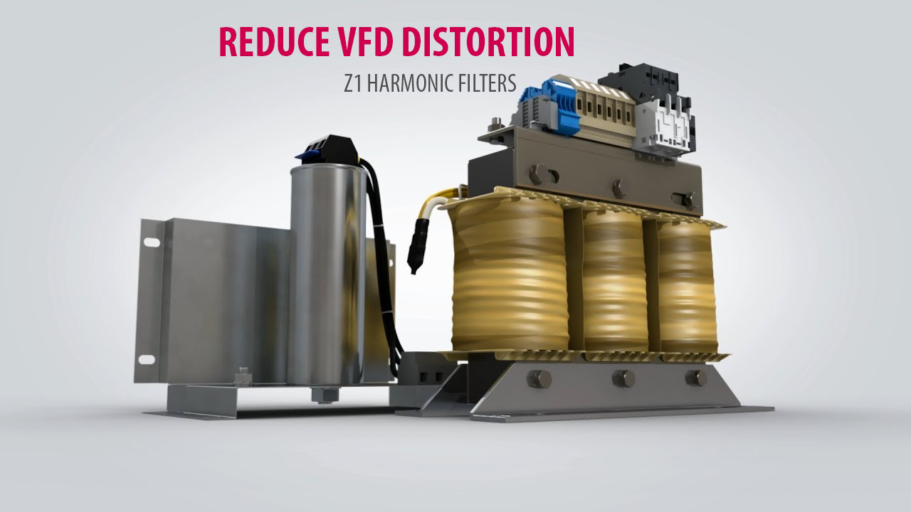
Harmonic Filter
Harmonic filters remove low-frequency harmonics from the electrical system. Variable Frequency Drives (VFDs) use a six-pulse rectifier in their input stage to convert the incoming AC voltage to a DC voltage. However, the design of the rectifier causes a non-sinusoidal current draw from the main line, which results in a current draw that looks like a sawtooth wave. This non-linear current draw produces current harmonics on the main line that are multiples of the main line frequency, such as the 3rd, 5th, 7th, and so on.

A harmonic filter is required if the system must meet the IEEE519 standard. EEE519 defines maximum current and voltage harmonic limits based on the system’s total demand distortion (TDD).
See the blog posts below for more information on harmonic distortion and the IEEE519 specification.
Read more: Harmonic Filters for Reducing VFD Distortion
Read More: Whitepaper-Applying-harmonic-filters-for-VFD-applications
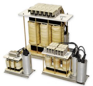
Based on the harmonic distortion limits required for the application, KEB offers both active and passive harmonic filters. The active harmonic filter actively measures the harmonic levels on the main line and injects harmonics in the opposite phase to cancel out the harmonic distortion created by the system. Active filters can achieve low harmonic mitigation levels of 5% or less.
A passive filter is a tuned inductor, capacitor system designed to filter out a specific range of harmonics (the 5th harmonic for example). Because of the passive nature of the filter, there is a limitation as to how much of the harmonics can be filtered out of the system. For this reason, passive filters typically will not achieve as low of harmonic levels as an active filter. The KEB harmonic filters can achieve levels of 8% or less when specific mains criteria is met. For many applications, a passive filter is sufficient to meet the application requirements. Contact KEB for more information.
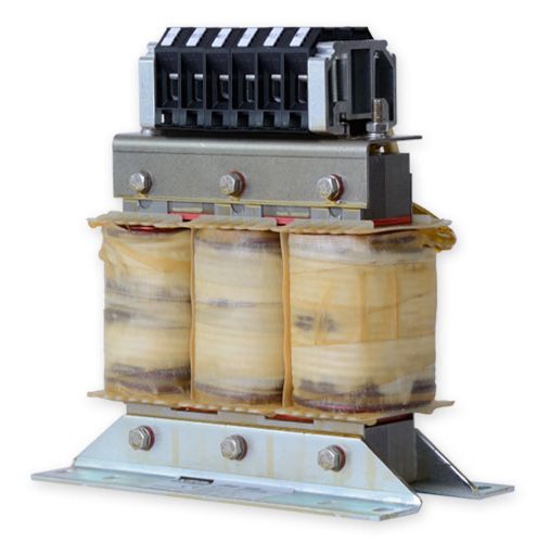
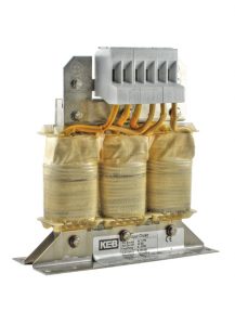
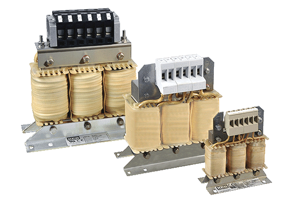
Input Reactor
Input reactors provide some protection for the VFD. Input reactors help reduce any voltage transients on the main line. The input reactor is a three-phase inductor that limits the rise time of the incoming voltage waveform. The limited voltage rise time reduces stress on the DC bus capacitors, increasing the system’s overall lifetime. Input reactors also help to reduce the in-rush current during the power-up of the VFD to reduce stress on the capacitors of the DC bus.
Output Filters
Sine Filter
A sine filter is an inductor/capacitor combination. The sine filter is a low pass filter used to filter the PWM output of the VFD to provide a sine wave output to the motor.
Read More: How Pulse Width Modulation in a VFD works
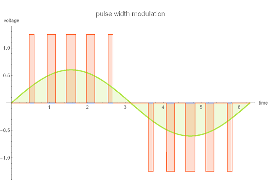
The sine filter is installed between the output of the VFD and the motor. The sine filter provides a sine wave current and voltage waveform on the motor side of the filter. This sine wave allows for the most efficient operation of the motor. The cleaning waveform also reduces heating of the motor windings, increasing the lifetime of the system.
Read More: KEB Sine Wave Filters
Sine filters are also used when long motor leads are required for the application. The sine filter should be installed as close as possible to the VFD, typically in the same electrical enclosure. Depending on the required output frequency to the motor, the cable length can then be up 500m or more.
Read More: Choosing Output Filters Based on Motor Cable Length
Output Choke
An output choke in an inductor system reduces the voltage rise time at the motor. Reducing the rise time of the output voltage helps protect the motor’s insulation system and can help reduce the motor’s operating temperature. If required, either an output choke or a sine filter are used, typically not both.
Read More: dV/dt Filters – Motor Chokes – Products
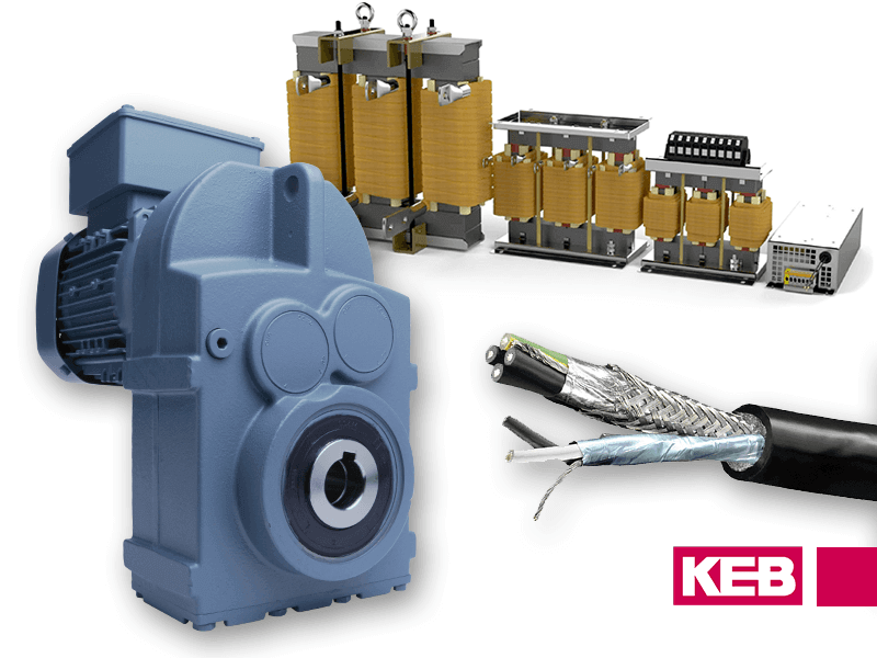
KEB’s Line of VFD Input and Output Filters
The advantages of VFDs are significant, but to ensure longevity and efficiency, OEMs must properly install input and output filters. KEB offers an expansive portfolio of VFD filter types for both power inputs to reduce harmonic distortion and electromagnetic interference (EMI), as well as conditioning the output power to reduce PWM and voltage rise time and create a sinewave to the motor. Contact us if you have any questions or need help engineering an ideal solution for your machine.
Related Articles
Let's Work Together
Connect with us today to learn more about our industrial automation solutions—and how to commission them for your application.