
Choosing Output Filters Based on Motor Cable Length
To determine if an output filter is needed based on the expected motor cable length of the application, a few system characteristics should be considered. The motor type, cable type (shielded or unshielded), the expected cable length between the VFD and motor, the VFD switching frequency, the expected output frequency to the motor, and the motor size, just to name a few.
The switching frequency of the VFD coupled with the cable type and length can potentially create a high voltage peak at the motor and or VFD terminals. This can contribute to premature aging of the motor insulation and reduce the operational lifetime of the components.
Motor cables have inductance and capacitance proportional to their length. Similarly, motors windings also have an inductance, capacitance, and impedance. An Impedance mismatch can result in a voltage ringing at the motor terminals. As the motor lead length increases, the overshoot voltage also may increase – potentially reaching levels that could be damaging to the motor.
Related Article: 7 Steps to Reducing EMI with VFDs
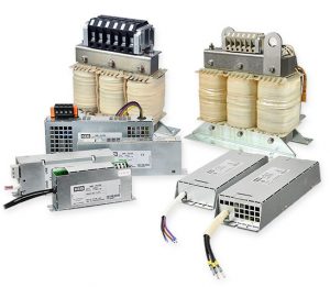
Comparison of Output Filter Types
Depending on the required motor lead length, motor type, and cable type, an output filter may provide a solution to help protect the motor and prolong the lifetime of the components. Below is a comparison of output filters, their benefits, and relative cost:
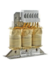
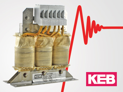
Motor Choke
Relative cost: $
Benefits:
- Reduces the dv/dt output of the VFD, which reduces the peak voltages at the motor terminals.
- Reduces motor rotor heating
- Increased motor winding/insulation life
Other Notes:
- VFD switching frequency ≤ 4khz.
- Output frequency ≤ 100Hz
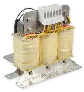
Sine filter
Relative cost: $$
Benefits:
- A low pass filter is designed to minimize voltage peaks and filter out the PWM voltage output of the VFD. Sinusoidal current and voltage waveforms phase to phase at the motor leads.
- Use on long motor leads (see table).
- Decreased audible motor noise
- Increased motor efficiency
Other Notes:
- The sine filter must be tuned to the VFD switching frequency
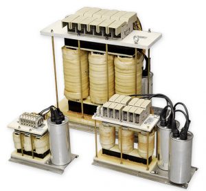
EMC sine filter
Relative cost: $$$
Benefits:
- Sinusoidal current and voltage waveforms phase to phase and phase to ground.
- Allows for unlimited motor cable length (subject to voltage drop limitations) when using an unshielded cable.
- Reduced EMC levels on the ground system.
Other Notes:
- The sine filter must be tuned to the VFD switching frequency
Shielded Cables and Motor Placement
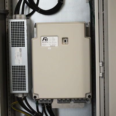
KEB recommends using a shielded motor cable to minimize the radiated electro-magnetic interference (EMI) which results from the high switching rate of modern VFD output transistors. A shielded cable utilizes a conductive sleeve, either foil or braided, around the cables. This shield provides a low impedance path for the EMI to ground.
Correct selection and placement of the motor cable is very important for high power motors and can offer the following advantages:
- Reduced stress of the motor bearings by bearing currents.
- Improved EMC characteristics.
- Fewer losses by leakage currents.
Recommendations:
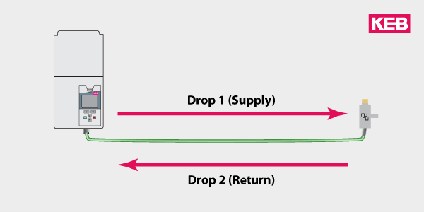
- Shielded motor cables can be connected in parallel between drive and motor to accommodate high current requirements.
- All three phases must pass through each shielded motor cable and all metallic fittings, otherwise, the high-frequency currents will create inductive heating in surrounding metal parts.
- Conductors of a high-stranded construction should be used to minimize skin effect losses. Additionally, the insulation temperature rating of the conductor should be a minimum of 90°C. The required cross-section of the conductor is described in the KEB power stage manual section => “Cable cross-sections”.
- To keep asymmetry as small as possible, all motor cables should have the same length and be routed together with minimum distance between cables. Large loops or gaps between phases must be avoided.
- The shielding must be grounded with large areas of surface contact on both ends (drive and motor). Use a metal clamp to contact the shield 360° around the cable. Using only the drain wires will significantly reduce the effectiveness of the shield.
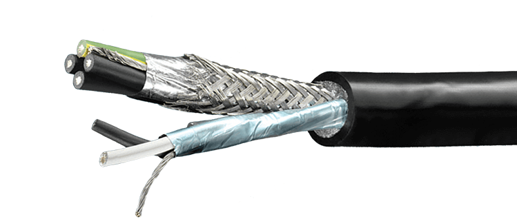
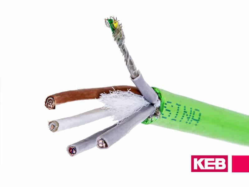
The recommended type of motor cable
Symmetrical shielded cables are recommended for high motor power. The protective ground conductor is made up of three symmetrical conductors interwoven with the phase conductor. This design is proven to reduce the risk of motor failure resulting from common-mode currents.
For EU installations:
- Cable designator: 2XSLCYK-J.
- Compliance with the requirements according to EN 12502-1…5
For North American installations:
- Cable designator: XLPE TR Type TC-ER
- Compliance with the requirements according to UL 1277, NFPA 79,
- Certification UL, CSA, CE
When individual conductors are used, then conductors according to UL 1284 type MTW insulation is preferred.
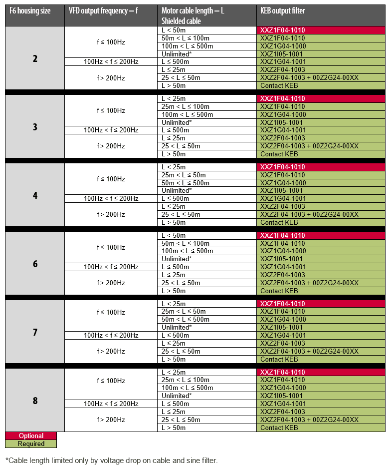
Recommended Output Filters
KEB output filter based on motor cable length and output frequency.
Shielded Motor Cable Output Filter Selection Chart
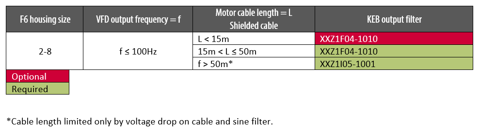
Unshielded motor cable Output Filter Selection Chart
If you would like to know more about KEB output filters and how we can improve your system, contact us today.
Related Articles
Let's Work Together
Connect with us today to learn more about our industrial automation solutions—and how to commission them for your application.