
Ask someone at a motor repair shop and they will tell you VFDs are hard on motors. Bearings fail due to VFD-caused bearing currents. Over time, insulation fails due to corona discharges. One scenario that is particularly stressful to motors is when the motor and VFD are mounted a large distance away from each other.
Long motor leads can lead to high voltage rises (or “dV/dt”) at the motor and can contribute to premature motor failure. This post describes VFD-related standing wave voltages and how to protect against them by using KEB dV/dt filters or what are sometimes referred to as dV/dt chokes.
What are dV/dt Spikes?
Most commercial AC VFDs use a technology called pulse-width-modulation (PWM) to simulate a 3-phase AC sinusoidal voltage output. PWM operates by rapidly turning the drive’s output insulated-gate bipolar transistors (IGBTs) on and off – Thereby modulating the DC bus voltage of the drive. When the IGBT is closed, the voltage at the VFD’s output terminals rises to that of the drive’s DC bus.
Related Video: How Pulse Width Modulation Works in a VFD
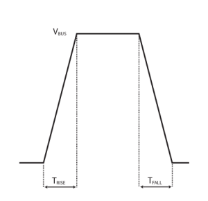
The change in voltage is not instantaneous but actually, ramps up to the DC bus level over a given time (TRISE). The rate at which the voltage increases is referred to as the dV/dt rise time and is a characteristic of the transistor design.
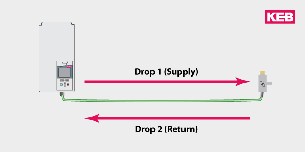
Motor Cabling & Reflected Wave
The cabling between the drive and the motor has a characteristic impedance that is dependent on the cable length and the physical properties of the cable material. The motor cabling acts as a transmission line and propagates the drive’s output voltage to the motor. If the impedance of the motor and cabling are not matched, a wave reflection will occur at the motor load – this results in a voltage overshoot or “ringing” at the motor terminals and a reflected wave back to the drive.
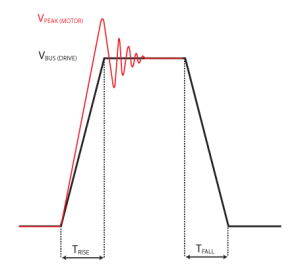
In a worst-case scenario, the reflected wave could be added to the fundamental waveform coming from the drive resulting in a significantly higher voltage at the motor terminals. Longer motor leads have larger impedances, ultimately increasing the voltage at the motor leads. For this reason, it is best to mount the motor and drive as close together as possible.
In practical terms, what does this mean? Let’s look at a typical VFD installation with a 25Ft. cable length and no dV/dt choke. At the motor terminals, we see a voltage of 988V even though the DC bus on the VFD is only 675V.
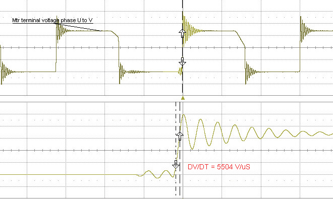
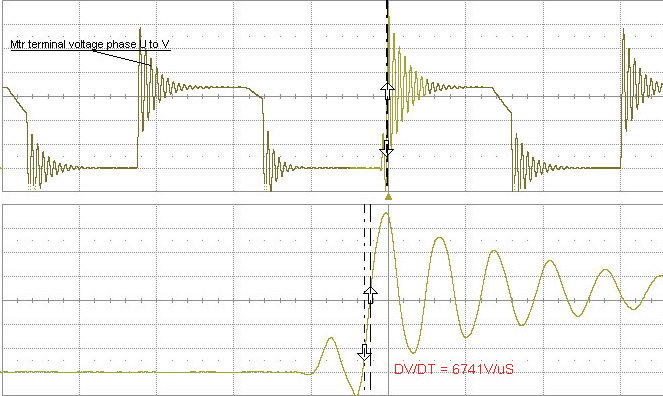
With the same setup, we now increase the motor leads from 25Ft. to 75Ft. in length. We are now seeing a max voltage at the motor terminals of 1,326V – double that of the DC bus!
dV/dt effects on motor operating lifetime
In short, voltage peaks from high dV/dt break down a motor’s insulation and shorten the motor’s operating lifetime. Most 3-phase AC motors produced today are “inverter-rated” and utilize wire and insulation rated to withstand peak voltages of at least 1600V. However, even if the dV/dt spikes never exceed the 1600V insulation rating, the repeated exposure to the spikes over the motor’s lifetime will stress and weaken the insulation.
Over time, the motor insulation system could break down – resulting in a phase-phase or phase-ground short in the windings and a catastrophic motor failure.
When Should I use a dV/dt Filter with my VFD?
1. Long cable runs
Any application that has long cable runs cannot be avoided or shortened. MRL elevator applications where the motor is mounted in the hoistway. Submersible pumps, HVAC equipment.
As a rule-of-thumb, KEB recommends the use of a dV/dt choke for runs greater than 40 feet.
2. High Switching Frequencies
KEB drives offer selectable switching frequency. Higher switching frequencies offer some application advantages. First, it reduces the VFD’s audible noise which is important in sensitive installations like an MRL elevator near the penthouse or with a theatre hoist. Second, higher switching frequencies provide the motor with a higher quality current waveform which results in lower motor losses and less heating.
Related to the discussion of dV/dt, it is important to note that higher switching frequencies require that the transistors turn on/off more times over a given period of time – Thereby, exposing the motor to an increased number of high voltage peaks. Operating at 16kHz will expose the motor to twice the number of voltage spikes compared to 8kHz.
So drive applications using higher switching frequencies should be especially concerned about dV/dt.
3. 480V Installations
Because the drive’s peak output voltage is directly related to the DC bus level, the dV/dt spikes will naturally be larger in 480VAC installations compared to those in 230VAC installs.
Extra precaution should be taken to mitigate the dV/dt spikes in 400-480VAC installations.
dV/dt Mitigation & Filters
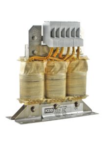
If the above items cannot be mitigated, a person should consider using a KEB dV/dt choke which will decrease the IGBT rise time and reduce the peak voltages at the motor. A dV/dt filter is placed directly at the output of the drive and limits the rate of change of the voltage (dV/dt) to a level characteristic of the filter design.
It is important that the filter is placed as close to the output of the drive as possible so the voltage peaks are not propagated through the motor cabling. Unless the motor and cabling impedances are matched, the standing wave reflection could still occur but the negative effects are dramatically minimized by the filtering of the dV/dt spikes.
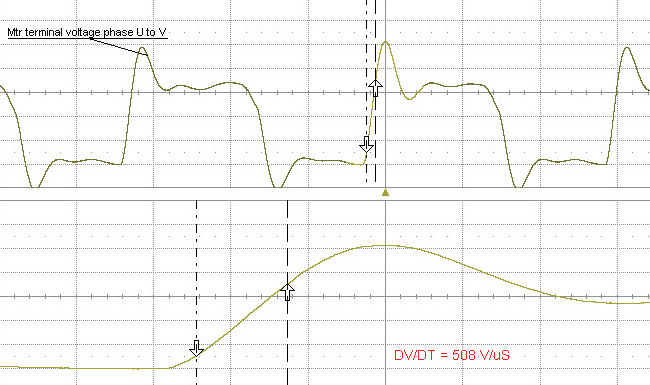
Let’s return to the previous example, and place a dV/dt choke on the drive with the 75Ft. cabling. The peak voltage is reduced from 1,326V to 951V – a 40% reduction.
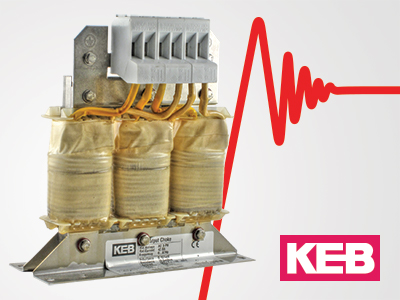
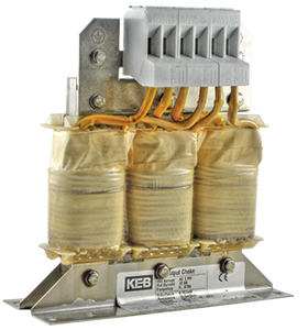
KEB dV/dt Filters
KEB dV/dt filters were designed specifically for demanding VFD applications – They offer high performance but are also commercially cost-effective. Some of the design features of the KEB dV/dt filters are:
- Feature: Low Inductance
- Benefit: Does not skew the motor model like common load reactors; can be used with PM and induction motors
- Feature: Operable up to 16kHz
- Benefit: Well suited for high-frequency VFD applications
- Feature: Minimal Insertion Loss
- Benefit: Efficient design with minimal power losses
- Feature: Small Footprint
- Benefit: Requires less panel space – Lower system cost
- Feature: Reduced EMI
- Benefit: Limits radio frequency emissions (> 250kHz)
KEB dV/dt Filters – Protect the Motor Investment
Do KEB dV/dt chokes sound right for your application? You can download a catalog on the dV/dt product page or Contact a KEB America engineer to discuss your application.
Related Articles

Let's Work Together
Connect with us today to learn more about our industrial automation solutions—and how to commission them for your application.