
This is how to quickly and effectively start-up an asynchronous induction motor using our F5 drive. Utilizing KEB’s programming software COMBIVIS 6, we can break down the programming process into 10 simple steps.
Specifically, we will be highlighting a KEB F5 startup in closed-loop control with encoder feedback. The general process will be similar for other motors and control types.
What do I need to Get Started?
Closed-loop control with encoder feedback is a VFD control method that utilizes measured speed feedback through an encoder device.
In general, there are five main components that will be required for a KEB F5 startup using your particular motor. They are:
- Power Source (F5 has AC 1-phase, AC 3-phase, and DC input options)
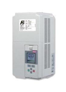
- F5 Drive
- 3-phase AC motor (Either induction or PM synchronous)
- Encoder feedback system
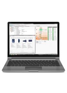
- COMBIVIS 6 programming software to configure VFD
Once we connect our power and devices in their respective manner, we can startup COMBIVIS 6 and soon begin programming.
Before We Begin
Connect the KEB F5 Drive to COMBIVIS 6 Software
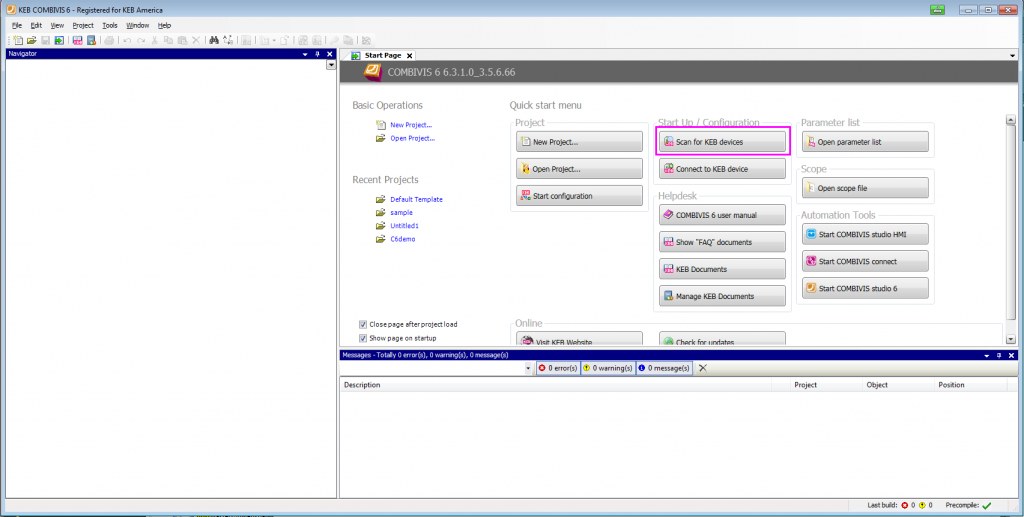
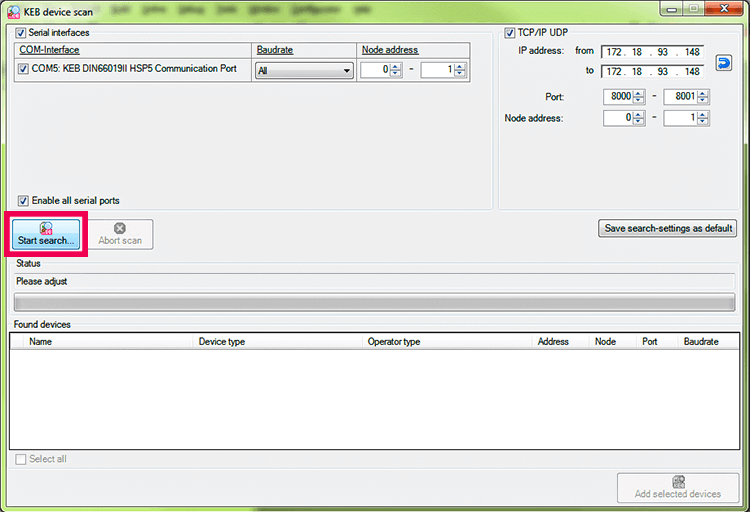
One option to scan for a device is on the start page of COMBIVIS 6
Before we can start programming, we first need to connect our drive to COMBIVIS 6 using the KEB USB-to-serial converter. We can then perform a device scan to locate the F5 drive.
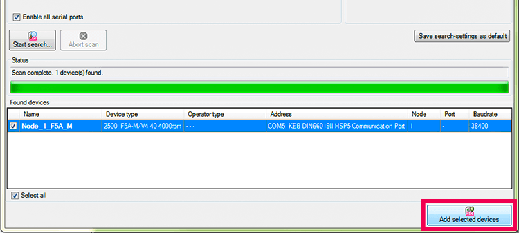
Once the F5 has been found, we can add the selected device to the COMBIVIS 6 project.
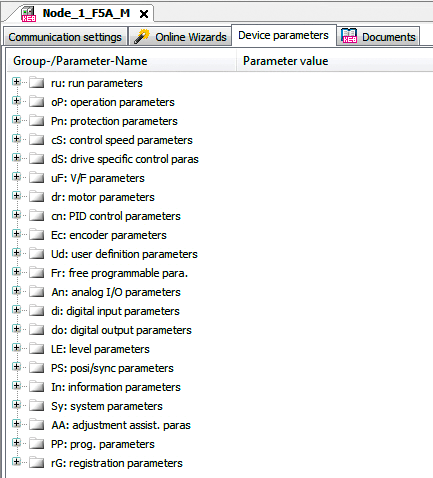
Once added to the project, we can see all of the F5 drive parameters inside the “Device Parameters” tab.
Now that all of our components are wired up and connected, we can dive into our 10 startup steps.
The 10 Steps to Starting a Motor
Unlike the S6 drive startup, the F5 drive does not have integrated programming wizards, and programming is strictly parameter-based. Therefore, we are going to create a startup parameter list to show how to quickly and easily program and start up the drive. Just for reference, the parameter list we are going to create is in accordance with the F5 Application Manual, which is available to customers at no charge. Please visit www.keb.de/my-account/registration to register.
I opened a blank parameter list and made visible only a few columns that we will need for our programming.
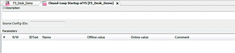
The “Offline value” column represents the desired value we are writing in our program and the “Online value” column displays the active parameter value inside a connected KEB drive.
Prior to starting Step 1, we must ensure that the F5 drive is disabled or is in a “noP” state. Programming the F5 drive while the drive is enabled will cause erroneous drive behavior.

Step 1 – Control Type and Speed
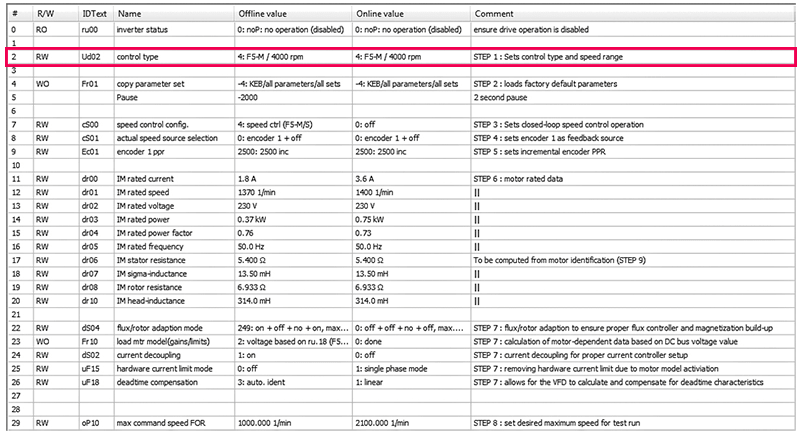
Starting with Step 1, we will set our Ud.02 control type to a value of “4: F5-M / 4000 rpm”. This sets the drive for operation of an asynchronous induction motor with a maximum attainable reference speed of 4000 RPM.
Step 2 – Enter Factory Settings
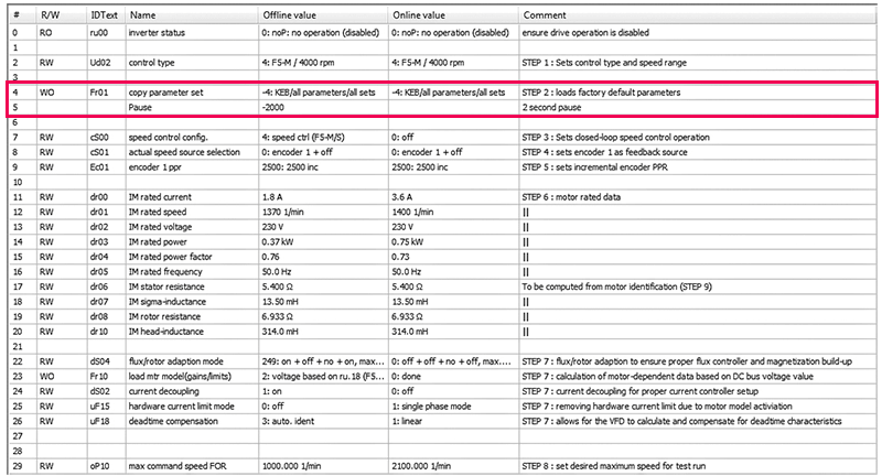
Step 2 of the parameter list sets the parameters inside the drive back to factory defaults using parameter Fr.01. This ensures we are starting our parameterization from scratch.
Step 3 – Configure Speed Control
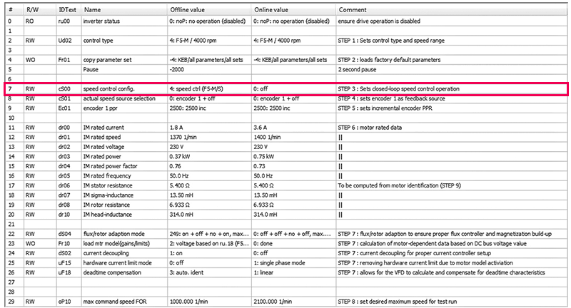
Step 3 has us setting the drive into closed-loop control with encoder feedback.
Step 4 – Set Feedback Source
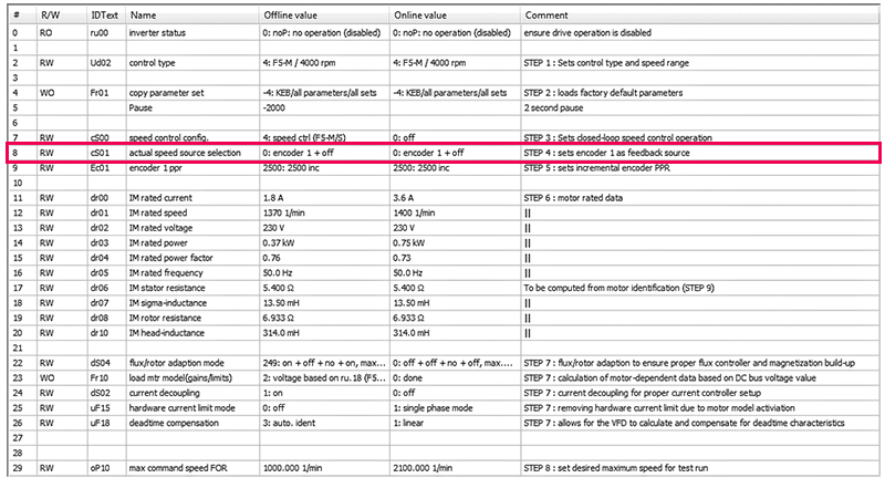
In Step 4, set the feedback source as encoder 1.
Step 5 – Set Encoder PPR Value
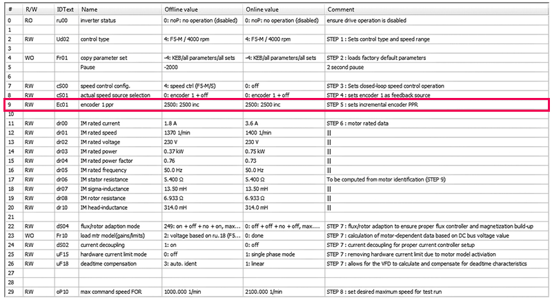
For our startup, we are using an incremental encoder, so we need to set the pulses per revolution, or PPR, in parameter Ec.01.
Step 6 – Enter Motor Rated Data
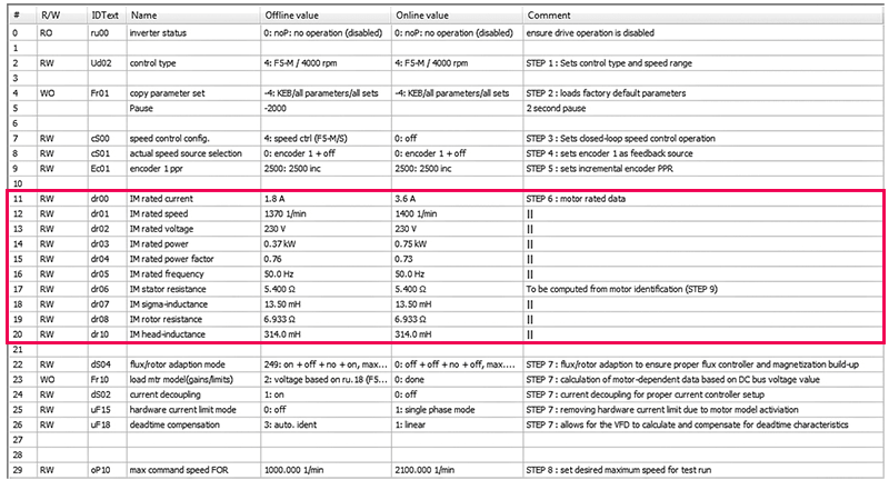
For Step 6, we need to enter our motor-rated data which is typically obtained from either the physical motor nameplate or a motor specification sheet.
We need the rated current, rated speed, rated voltage, rated power, rated power factor, and rated frequency of the induction motor. The resistance and inductance values found in parameters dr.06 – dr.10 will be computed automatically during the motor identification in Step 9.
Step 7 – Modify More Parameters
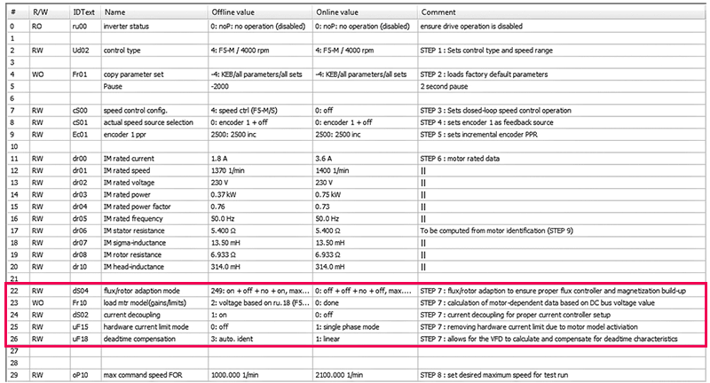
For Step 7, we are going to modify a few parameters that are integral for successful operation in closed-loop control. These parameters turn on current decoupling, allow for motor model activation, and set proper flux control. These parameters are assigned in accordance with the F5 Application Manual.
Step 8 – Set Maximum Command Speed
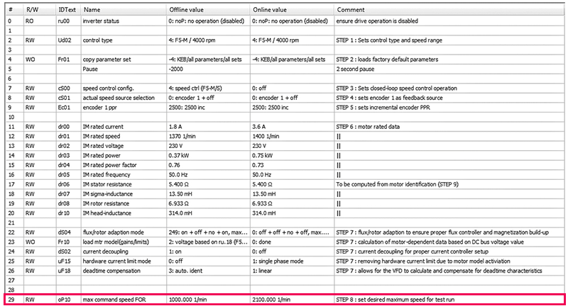
In Step 8, we will set our maximum command speed for this startup.
Now that we have completed Step 8, we have completed our programming and we are now ready to download our parameter list into the F5 drive.
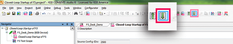
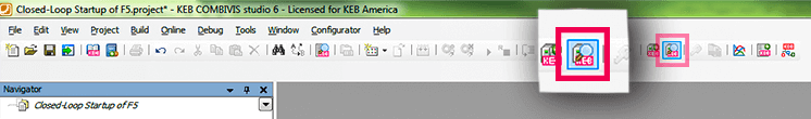
We can download the parameter list into the connected F5 drive by going to the green down arrow in the toolbar, which reads “download list to the device.” Click “Yes,” to download. The list will download into the drive. The parameter download process then begins and writes the “Offline value” column into the “Online value” column.
Step 9 – Motor Identification
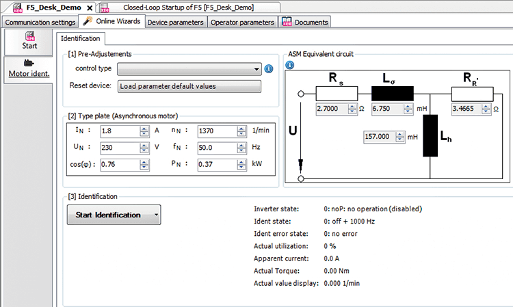
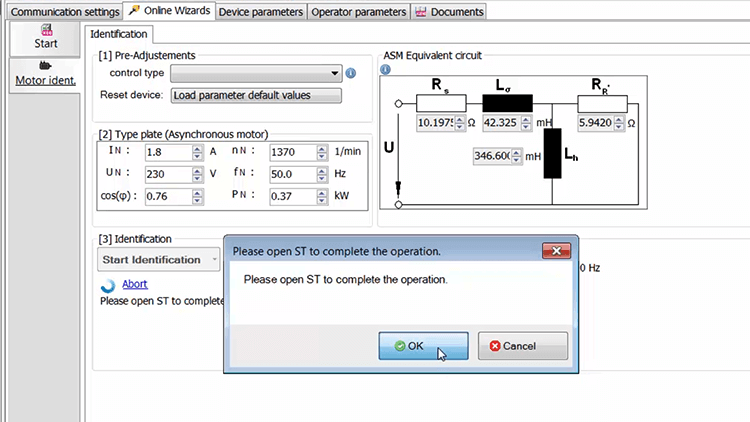
Now that the drive has been programmed, we are able to move to Step 9, which is our motor identification. We can access the motor identification by first navigating to the drive tab, then going into the “Online Wizards,” and finally selecting “Motor ident.”
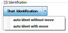
In box [1], there are no required changes since the drive has already been programmed and adjusted via the parameter list download. In box [2], we must confirm the rated nameplate data of our particular motor. Moving to box [3], we must first click the drop-down arrow next to “Start Identification.”
Caution:
Selecting the “auto ident with move” option will cause the motor shaft to rotate. This identification mode should only be utilized under no-load conditions. If your motor is loaded or coupled to any other mechanical components, it is imperative to use “auto ident without move” for safe and successful motor identification.
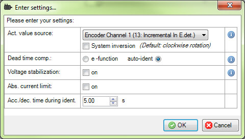
After selecting “auto ident with move” in the case of this startup, you will be prompted to confirm the motor-rated data once again. After that, another popup will appear asking to confirm the actual speed value source as encoder 1 – we will click OK.
During the identification process, the motor may rotate, and also different audible noises of varying frequencies may be heard which is normal during the identification process. The identification process may take anywhere from 30 seconds to a few minutes depending on the system. We will click “OK” to start the identification.
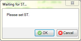
Now we’ll set the ST/control release and begin the identification.
Motor identification was completed successfully.
Step 10 – Test the Motor
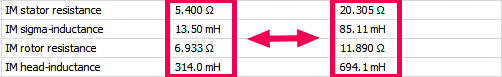
Once the motor identification is complete, we can look back at the parameter list and see the inductance and resistance values have been modified in real-time in the F5 drive due to the motor identification.
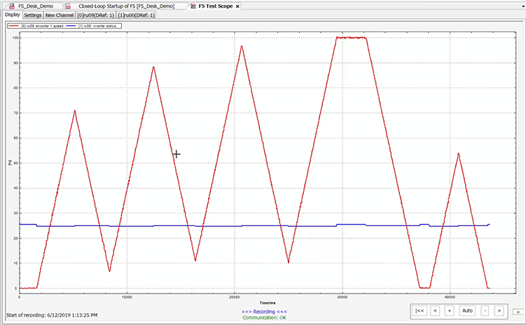
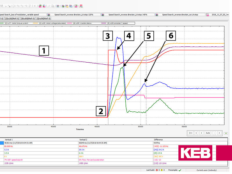
We are now ready to test our motor. For Step 10, we will use a potentiometer connected to an analog input which will allow us to adjust the speed control of the drive for this test. A COMBIVIS scope trace showing encoder speed and inverter status is shown below.
F5 Startup Conclusion
You have now quickly and effectively started a motor with a KEB F5 Drive.
You may have noticed that there are approximately 20 parameter groups within an F5 drive, many of which were skipped over or not used during this startup. There are many other important parameters that you would visit to complete the commissioning of your drive and motor for successful integration into your industrial machine.
If you are interested in visiting with KEB sales or engineering regarding your new application, please contact us using the form below.
Related Articles
Let's Work Together
Connect with us today to learn more about our industrial automation solutions—and how to commission them for your application.