
Introduction to electromagnetic interference with VFDs
This is the first of two articles describing what electromagnetic interference (EMI) is, how it affects electrical components in the electrical panel, and common tips that can be used to limit the effects of EMI.
Read the next EMI series article: 7 steps to reduce the negative effects of EMI.
What is EMI?
Electromagnetic interference (EMI) or radio frequency interference (RFI) is described as electromagnetic signals that interfere with the normal operation of electrical equipment. EMI can create adverse effects with electrical components in the elevator control panel, contributing to a loss of serial communication, nuisance drive trips, and disturbance of control signals. EMI not only degrades the performance of electrical equipment but also decreases the lifetime of components and increases the financial cost to maintain equipment.
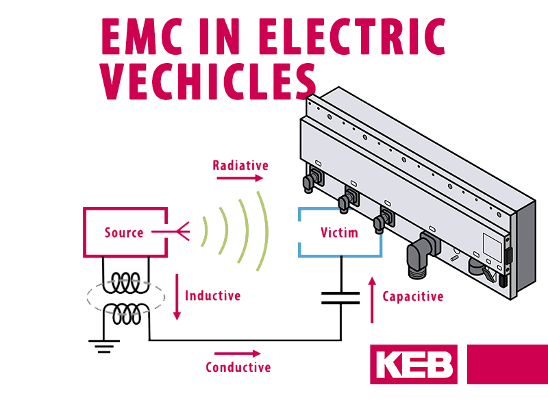
Conducted and radiated EMI are two main types of high and low-frequency interference that must be considered when troubleshooting potential sources of EMI. As you read, keep in mind each type of interference problem includes a source, a receptor, and a transmission path between the source and victim. This concept is illustrated below:

Conducted EMI is defined as interference that uses conductors as a path from a source to a receptor. For example, a motor encoder grounded to a noisy connection would conduct noise to the drive encoder interface. The conducted noise could cause the drive encoder interface to receive inaccurate voltage signals preventing the elevator drive from interpreting the motor speed correctly or drive faults.
Initially, it may be assumed that the root cause of the drive operational issues is related to an incorrect parameter setting or possibly a faulty drive interface board. Closer inspection reveals the culprit to be the poor grounding of the encoder cable.
Radiated EMI is defined as interference that uses a wireless path from a source to the victim. This is commonly seen in elevator control panels with AC motor wires are laid in parallel next to low-voltage control wiring. The result is coupling between the wires causing disturbances on the data transmission line. For example, if the motor wires were laid in close proximity of a serial link between the PLC and the VFD, the coupling of the signals may corrupt the data packets being transferred between the controller and drive.
How is EMI related to VFDs?
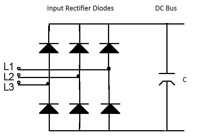
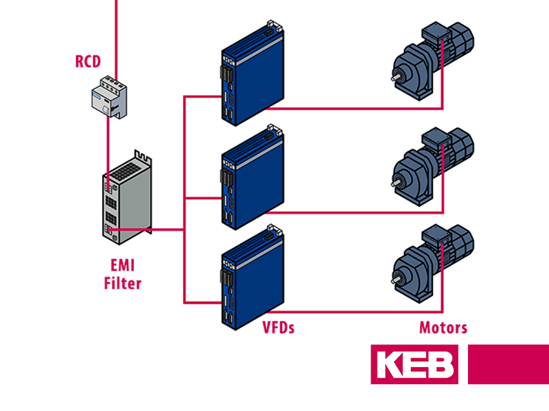
Drive Topology
EMI is created by a VFD’s input rectifier stage which consists of a full-wave diode bridge that rectifies the incoming AC power into DC power. The input rectifier draws a non-sinusoidal current from the power supply during each period of AC voltage. This creates current harmonics on the power supply and subsequent voltage distortion which can be conducted to other electrical equipment connected to the utility.
Related Video: How Pulse-Width Modulation Works in a VFD
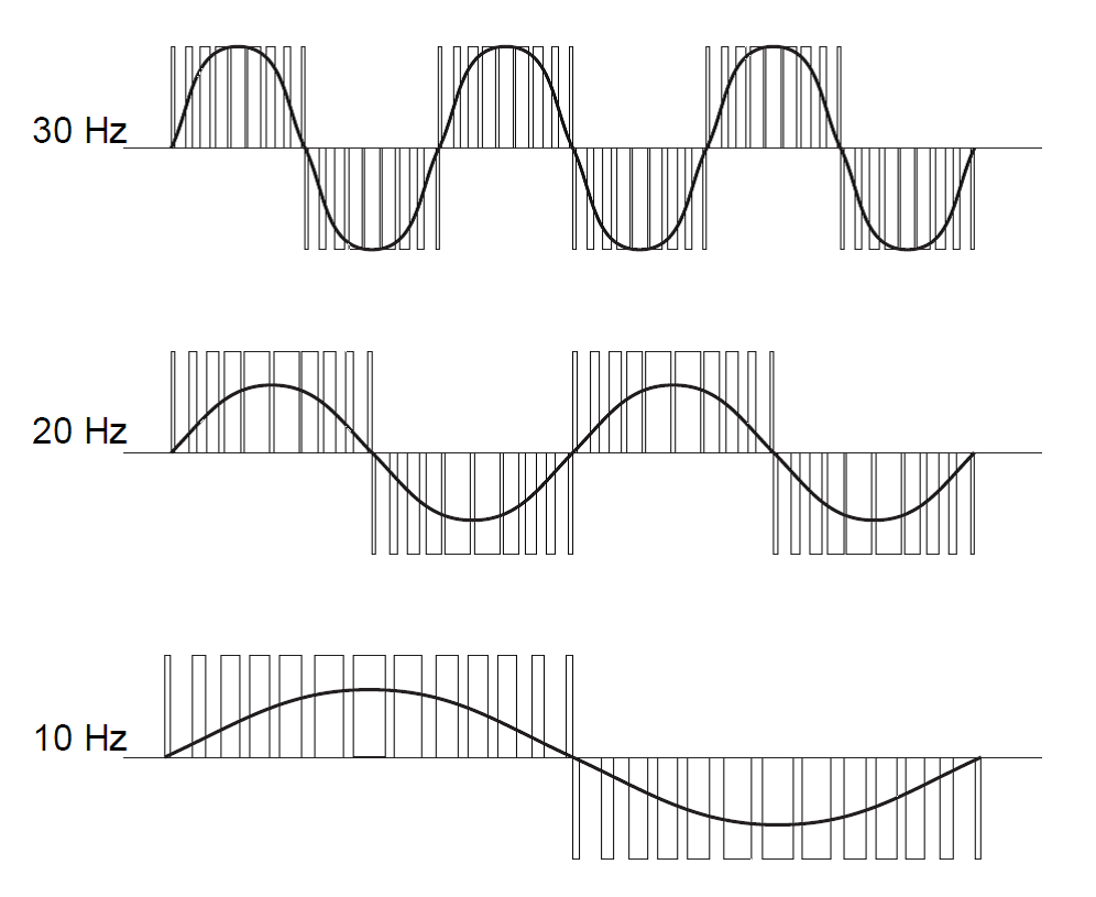
Pulse-Width Modulation
VFD’s use pulse-width modulation (PWM) to provide a voltage to the AC motor. The VFD output transistors modulate the DC bus voltage by turning the transistors on and off at a very high frequency (in the order of 8kHz) to simulate an AC waveform with a desired frequency and output voltage. A higher switching frequency has the advantage of providing a more sinusoidal current waveform to the motor, however, there are several trade-offs to consider.
Related Video: How do Switching Frequencies Affect Harmonic Distortion
During IGBT turn on the voltage at the VFD’s output terminal rises to that of the DC bus, the rate at which the voltage rises is referred to as dV/dt rise time. High dV/dt rates on the motor side of the VFD result in radiated electric fields, and voltage spikes that are conducted along with the motor cabling. It should be noted that the output of a VFD is especially rich in EMI noise due to the high-frequency transistor switching. This is important when considering how to lay out control and power wiring.
EMI – Knowing is half the battle
EMI is described as electromagnetic signals that interfere with the normal operation of electrical equipment. EMI problems often result in poor equipment performance and increased maintenance costs throughout the lifetime of the system. EMI is transmitted to a receptor device from a source via conduction and radiation. EMI problems caused by elevator VFD’s can be attributed to the non-linear components of the VFD drive and the high-frequency PWM switching of the output transistors.
The next article in the series will cover 7 tips to help mitigate EMI-related issues.
Related Articles

Let's Work Together
Connect with us today to learn more about our industrial automation solutions—and how to commission them for your application.