Back to Blog
Applications and How-Tos, KEB Technology

5 Essential Elements of a Quality Feedback Cable

Jeff Kardell | September 6th, 2024
Featured Products

Using a quality feedback cable leads directly to maximized performance in servo motors. As the saying goes, “A chain is only as strong as the weakest link.”

It does not make sense to invest a lot of money in a high-torque servo motor, servo amplifier, and planetary gearhead and then cut corners with an inferior feedback cable since the entire system performance will suffer.

At the time of writing, our longest successful servo installation uses a 100-meter (EnDat) cable. How can you effectively transmit a 5V signal the length of a football field? It is only possible with a high-quality cable that eliminates unwanted noise and interference.


Why a Quality Feedback Cable is Important

The importance of high-quality feedback cables in servo systems cannot be overstated. While it might be tempting to cut costs on cabling, this often leads to false economies.

Servo motors, the workhorses of many manufacturing and process control applications, rely on accurate position feedback to maintain precise control.

This feedback is transmitted through cables that must withstand harsh environments, electromagnetic interference, and constant motion without degrading the signal quality.

Potential consequences of using inferior cables include:

  • Intermittent system failures due to EMI susceptibility
  • Reduced accuracy from signal degradation
  • Shortened lifespan, especially in dynamic applications
  • Safety risks from electrical hazards

A feedback cable can make or break a system’s performance in industrial automation, where precision and reliability are paramount.


5 Elements of a Feedback Cable

Today, we will look at five aspects of a quality feedback cable that you should keep in mind when choosing a solution for your application.

Each of these elements plays a crucial role in ensuring the integrity of the feedback signal, affecting the overall performance and longevity of your servo system.


1. Shielded Twisted Pairs

Most position feedback systems will utilize differential signal pairs, which benefit long cable runs and noise immunity. A differential pair includes the primary signal (e.g., 0 …5V signal for TTL) and the complement or opposite of that signal.

In theory, by twisting these signal pairs together, their magnetic fields will cancel each other out and reduce crosstalk from other pairs. A shield is then placed over each conductor pair to further prevent external EMI from coming on to the conductors.
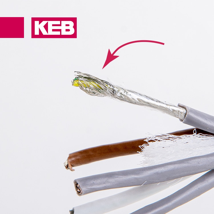
In industrial environments, shielded twisted pairs are essential for protecting feedback signals from electromagnetic interference. This design creates a balanced transmission line that’s inherently resistant to external noise, which is crucial for both analog and digital signals.

The individual shielding of each pair provides an additional layer of protection, particularly important for high-resolution feedback devices like absolute encoders. In applications requiring sub-micron precision, such as semiconductor manufacturing or high-precision machining, the integrity of these shielded twisted pairs can significantly impact operational success.


differential feedback signals
Ideally, use differential signals. The conductor pair should be twisted and housed with a braided shield.


2. Overall Shield Over All Conductors

Next, a second overall shield, preferably braided, is placed over all conductors in the feedback cable. This type of shielding again helps to prevent EMI from entering the cable. This is especially important since the feedback cables are likely running in a panel with high power and VFD switching transistors.

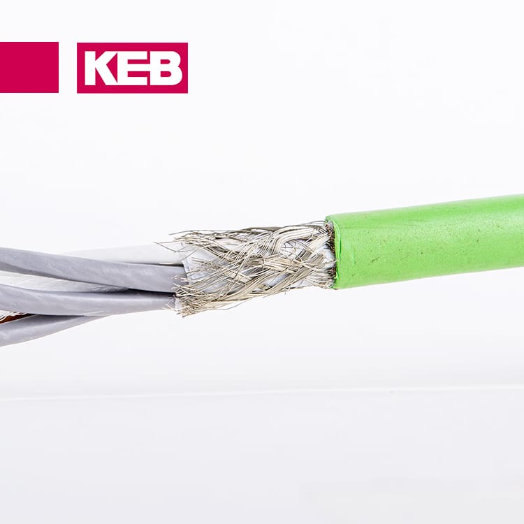
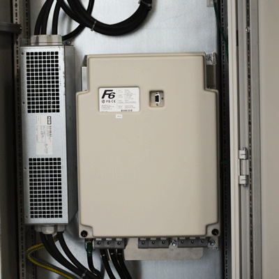
The picture below shows a feedback cable that utilizes both shielded twisted pairs – as well as a braided shield over the entire cable. The overall shield is connected to ground and provides a path to drain high-frequency noise from the feedback system.

This overall shield acts as a comprehensive EMI barrier, creating a Faraday cage effect around the entire cable assembly. It’s particularly beneficial in environments with variable frequency drives (VFDs), which generate significant high-frequency noise.

The braided shield offers superior flexibility and durability compared to foil shields, which is crucial for applications involving frequent cable movement.

Proper grounding is essential for shield effectiveness. The overall shield should typically be grounded at only one end, usually the drive end, to prevent additional noise introduction from ground loops.


All signal conductors should be sheathed with a drain shield.


3. Tough Sheath Material

The material of the feedback cable is significant. It is important to have a sheath that consists of an abrasion and cut-resistant material. In manufacturing environments, it is common to have many sharp edges and materials that the cable can catch on.

Using a material that can withstand those conditions is highly recommended.

KEB’s standard feedback cables include an outer sheath made of Polyurethane, which is extremely wear-resistant and mechanically tough for harsh environments while still being flexible and age-resistant. Other cable sheath materials are available if you plan to be around chemicals or oils that would degrade the Polyurethane material.

The choice of sheath material extends beyond physical protection to include environmental resistance. In food processing plants, for instance, cables may need to withstand frequent washdowns with caustic cleaning agents.

Polyurethane sheaths, like those used in KEB’s cables, offer an excellent balance of flexibility and durability, perfect for dynamic cable management systems in CNC machines or robotic arms.

For extreme environments, such as offshore oil rigs or chemical plants, specialized materials like PTFE might be necessary for their exceptional chemical resistance and temperature tolerance.


feedback cable sheath
The outer protective shield should resist abrasion, nicks, and any contaminants.


4. Bend Radius and Cable Flex

The bend radius is the radius at which a feedback cable can be bent without damaging it – and should be specified by the manufacturer.

To ensure reliability and a long cable service life, you must ensure that your application’s bend radius is greater than the recommended minimum bend radius of the cable you choose.

In some applications, like a gantry or robotic system, the feedback cable must bend repeatedly as the machine moves. A user should check that the selected feedback cable is capable of this type of application.

Manufacturers should list the cable’s “bending cycles,” which provides information on the expected lifetime of the cable in dynamic applications. In general, KEB encoder cables are robotic grade and support many bend cycles.

Adhering to the specified bend radius maintains cable integrity.

Excessive bending can lead to conductor strain, shield damage, and insulation stress, potentially causing increased resistance, EMI protection loss, or even short circuits.

For dynamic applications, the “bending cycles“ specification becomes critical, indicating how many flexes a cable can withstand before failure.

Temperature also impacts flexibility. Cables can become stiff in cold environments or deform under stress in high temperatures.

Therefore, when selecting cables for dynamic applications, consider the full range of environmental conditions they will face.


5. Connectors

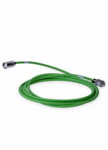
There are many options for connectors on feedback cables, and it is a critical component of your selection. Screw-in connectors can be utilized to reduce strain on the cable in small installation spaces.

As a rule of thumb, a prefabbed cable with terminated connectors is always preferred for noise immunity. Terminated connectors also make for a quicker installation and reduce the likelihood of miswiring in the field.

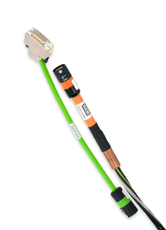
KEB’s feedback cables are equipped with connectors to ensure compatibility with KEB drive and motor products. Although it is possible to terminate your connectors from cable stock, purchasing a prefabbed cable that has been QA tested is likely faster and easier.

High-quality connectors for servo feedback cables often feature:

  • 360-degree shielding for optimal EMI protection
  • Gold-plated contacts for superior conductivity and corrosion resistance, and
  • High IP ratings for harsh environment protection.

The connector’s design significantly impacts overall reliability. Features like strain relief and robust locking mechanisms prevent failures due to vibration or repeated mating cycles.

While field-termination is possible, it requires specialized tools and expertise to ensure proper shield termination and signal integrity, making pre-fabricated cables the preferred choice for most applications.


Adding Connectors in the Field

In certain situations, purchasing a pre-fabricated cable will not be an option for your application.

For example, perhaps a special connector is required, or a connector must be changed in the field. In this case, either the motor or drive side connector can be modified.

Remember these principles when connecting a feedback device to a KEB drive:

  • The outer shields are tied to the metal connector housings on both ends. These housings connect to the Earth ground.
  • The internal twisted pair shields are connected on the drive side to 0V common. The internal shields on the motor/encoder side are clipped short and not connected.
  • Always follow the instructions of the connector manufacturer when modifying a feedback cable. This might require a solder connection or specially crimped connectors.
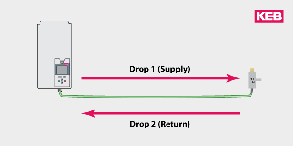
  • One complete run is optimum. Avoid terminal strips and “breakout” boxes whenever possible. These disrupt the EMI shielding and act as an EMI entry point.

When field modification is necessary, maintain cable integrity and shielding effectiveness. Use proper tools designed for specific cable and connector types to avoid intermittent connections or signal degradation.

Maintain the original twist ratio of pairs as close to the connector as possible, and ensure the overall shield makes a 360-degree connection to the connector’s shell.

After modification, perform comprehensive testing including continuity, insulation resistance, and signal quality tests. Document all modifications for future reference or troubleshooting.

Remember, field modifications should be approached cautiously and performed by qualified personnel to avoid immediate signal integrity issues and long-term reliability problems.


Use a Good Feedback Cable and Sleep Better at Night

People use inferior feedback cables for a variety of reasons, including cutting costs, the need to splice connectors or roll your own, or even “I found an old cable in R&D.” But don’t get caught in this trap – remember the above principles and use high-quality cabling.

Investing in high-quality feedback cables is integral to your overall system design. The cost difference between high-quality and inferior cables is often negligible compared to the potential costs of system downtime, troubleshooting, and reduced performance.

As industrial automation systems become increasingly complex and interconnected, it stresses the reliability of each component. A single point of failure in a feedback cable can potentially halt an entire production line.

Have problems or a special application? Contact a KEB engineer to discuss your application today. Our team of experts can help you select the right feedback cable for your specific needs, ensuring optimal performance and reliability for your servo system.

Contact Us

Let's Work Together

Connect with us today to learn more about our industrial automation solutions—and how to commission them for your application.

  • This field is for validation purposes and should be left unchanged.