
Simple drive applications can be solved by many drive vendors. The difference in drive performance and quality becomes more apparent in difficult and demanding applications.
An example of a more difficult application is one that uses a Master-follower (or “Master-slave”) drive topology. Master-slave drive applications can be seen on many machines including winder/unwinders, printing presses, and gantry cranes, to name a few. This post gives an overview of some of these applications and what drive technology to look for in order to meet the tough demands.
History of Master-Follower Applications
How do I synchronize motor speeds? It’s a common question. In the past, early machines might have used one large electric motor that used a long line shaft. That one central line shaft would have many belts and cams that would mechanically fix the different axes together.

This machine design left a lot to be desired – belts could slip, line changes were very difficult, etc. There are now better options with Master-follower drive topologies where an individual motor is used for each axis.
What is a Master-Follower Application?
A Master-follower application is where two or more drives are electronically synchronized together. Typically, the first drive is configured as the “Master” or “Leader.” Subsequent drives that follow the master are referred to as the “Slaves” or “Followers.”
Load sharing, synchronization, and redundancy are common reasons that master-follower arrangements are used. Since the shafts are only electronically coupled, machine operation can be changed with a few parameter adjustments – this is a far cry from the early mechanical line shafts where changes were difficult. This flexibility allows for quick line changes where machines can quickly accommodate a recipe update and change product sizes.
Master-Follower Control Signals
The master can provide a following signal to the slave in a few different ways.
Analog Output/Input Speed Reference
The speed reference from the master can be a simple analog output based on the output frequency. The analog signal is then fed into the slave drive(s). This topology allows open-loop VFDs to be used and is going to be the most cost-effective option. I have seen this topology used effectively in conveyor and flight simulator applications.
However, the response between the motors might “lag” from the master to the follower. The lag will increase as more axes are added. Additionally, without the use of an encoder, there is no feedback from the slave to correct the motor slip and variable loading. This topology should really only be considered for low dynamic systems that can tolerate more following an error. Machines requiring tighter synchronization will use encoder feedback.
Using Encoder Feedback
Improved speed regulation can be achieved by adding motor feedback into the Master. Then, the master provides a speed reference signal to the slave through a buffered TTL signal. This requires closed-loop drives with encoder cards but the result is going to be a much tighter speed regulation.
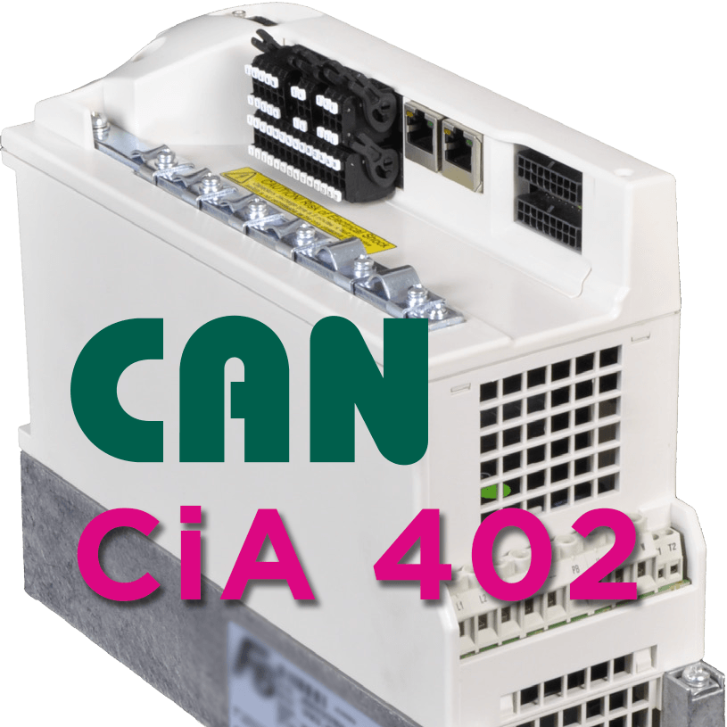
Demanding speed following applications will require drives that are able to read and process encoder signals quickly. KEB’s S6 Servo drive, for example, has a TTL encoder input that can be used up to 300kHz.
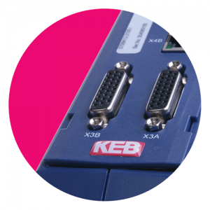
All KEB closed-loop drives also feature dual-channel feedback cards. One encoder channel can be an input – either from a motor encoder or from another drive. The second channel can be programmed as an input or as a TTL output which can then be coupled to the next slaved drive.
Using real-time bus systems
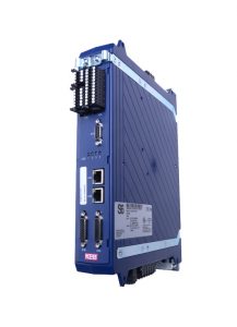
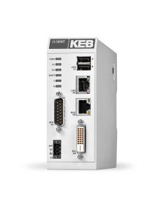
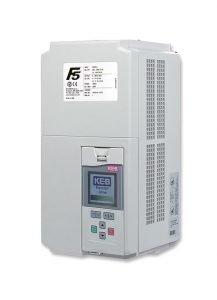
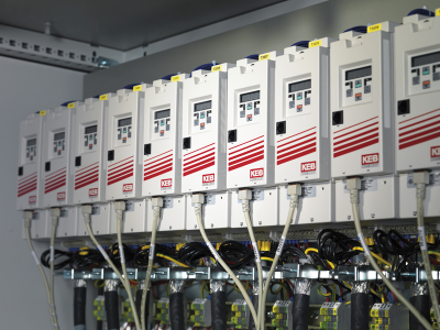
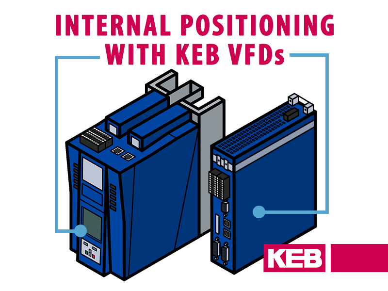
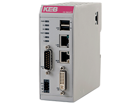
KEB’s F5 drives allow the Master-follower functionality to be programmed right in the drives. This includes scalings, gearing ratios, offsets, etc. But the most demanding applications will use a motion control capable PLC like KEB’s C6 SMART.
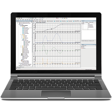
The SMART is an EtherCAT control that acts as a “virtual master” and handles the synchronization over the bus. KEB’s COMBIVIS programming software offers pre-made function blocks that make complex synchronization and camming very easy to set up.
High-performance applications will benefit from using real-time deterministic bus technology. For example, the high-speed EtherCAT process data in the S6 servo drive is updated at a rate of 250uS which is going to be much faster than the update rate for the previous control examples.
The S6 handles more communication types than most other servo drives – we have options for all deterministic real-time buses like EtherCAT, Powerlink, and Profinet IRT. Bus systems have the added benefits that they are less susceptible to noise issues and can be used over long distances.
Types of Master-Slave operation
There are different implementations of master/follower arrangements but here are some of the more common applications.
Speed/Velocity Following
In this application, a user wants multiple motors to run at the same speed (or perhaps at a scaling of each other). The master operates in velocity control mode and typically has some sort of system feedback like a pressure sensor or motor encoder feedback. The master then outputs a speed reference command to one or more slave drives. If the different drive axes are geared differently, then the follower speed command might be a scaled version of the master speed command. It is also possible to apply a speed offset.
The important thing to note in speed following mode is the drives are always trying to regulate the instantaneous speed command. So, if there was a following error that happened in the past, the follower drive just tries to correct the speed setpoint but does not compensate for any accumulated error.
Positioning Following (Angular Synchronization)
Angular synchronization is where the master axis provides a position reference to the slave axis. This is also sometimes referred to as “Angular synchronization” since the rotary position is angular. Because we are dealing with position control the drives are closed loop with some sort of feedback on each axis.
The slave axis must follow the position reference. Any sort of error by the slave axis must be corrected as quickly as possible. Angular synchronization applications are even more difficult than speed following applications as the position loop needs to be closed at a much higher frequency.
An easy example to see this is a printing press where four colors are applied by separate roller axes. When the 4 axes are synchronized perfectly the result is a clear printed picture. When one axis has a position error and lags, that respective color becomes offset and the picture becomes distorted.

Load Sharing (Torque Sharing)
Torque sharing is also possible with master-follower arrangements. Torque sharing might be desired as a way to distribute the torque and work through different drivetrains and motors.
It also might be desired for its redundancy in critical applications (eg. solar panel tracking or wind turbine control). In normal operation, the drives and motors share the load resulting in less heating and wear on the mechanical components. If one drive does fail, the other axis is able to drive to a safe location or operate at a reduced state temporarily.
For load sharing applications it works best to assign slightly different torque values for the master and slave so they do not fight each other. For example, the master might be set to regulate at 51% of the torque command. Whereas, the slave axis might be set at 49% of the torque command.
Basic load-sharing applications (fans, pumps) can be achieved economically by using one drive and multiple motors. However, this topology has some limitations. In addition to improved speed regulation performance, one advantage with a torque sharing topology is that the drive can be used to detect overloads and motor sizes can be different.
Conclusion
In summary, the ability to implement master-follower applications is an important tool in a machine builder’s kit. KEB offers different technical solutions for different price points and performance levels. Contact one of our engineers to discuss how we can help you build a better machine.
Do you have a master-follower drive application? Let’s discuss how KEB’s high-performance drives can help improve machine performance.
Related Articles

Let's Work Together
Connect with us today to learn more about our industrial automation solutions—and how to commission them for your application.